
Hydraulic brake assist device

An auxiliary device and oil pressure technology, applied in the direction of hydraulic brake transmission, bicycle accessories, bicycle brakes, etc., can solve the problems of overturning or skidding, rolling, people and vehicles, damage, etc., and achieve the effect of production cost and easy installation

Inactive Publication Date: 2017-05-17
ANSURE
View PDF7 Cites 0 Cited by
  • Summary
  • Abstract
  • Description
  • Claims
  • Application Information

AI Technical Summary

Problems solved by technology

But also because the braking efficiency is higher, it is easier to control the front wheel brakes first in an emergency or when the brakes are not properly controlled (such as high-speed or down-wave sections), or when the braking force of the rear wheel brakes is lower than that of the front wheels. Causing people and vehicles, overturning or skidding and rolling, sometimes even causing serious casualties, damages

Method used


Image

  • Hydraulic brake assist device
  • Hydraulic brake assist device
  • Hydraulic brake assist device

Examples


Embodiment Construction

[0060] In order to understand the technical features, content and advantages of the present invention and the effects that can be achieved, the present invention is hereby combined with the accompanying drawings and described in detail as follows with embodiments, and the purpose of the drawings used therein is only for illustration It is not necessarily the true proportion and precise configuration of the present invention after implementation, so it should not be interpreted or limited to the scope of rights of the present invention in actual implementation based on the proportion and configuration relationship of the attached drawings. .

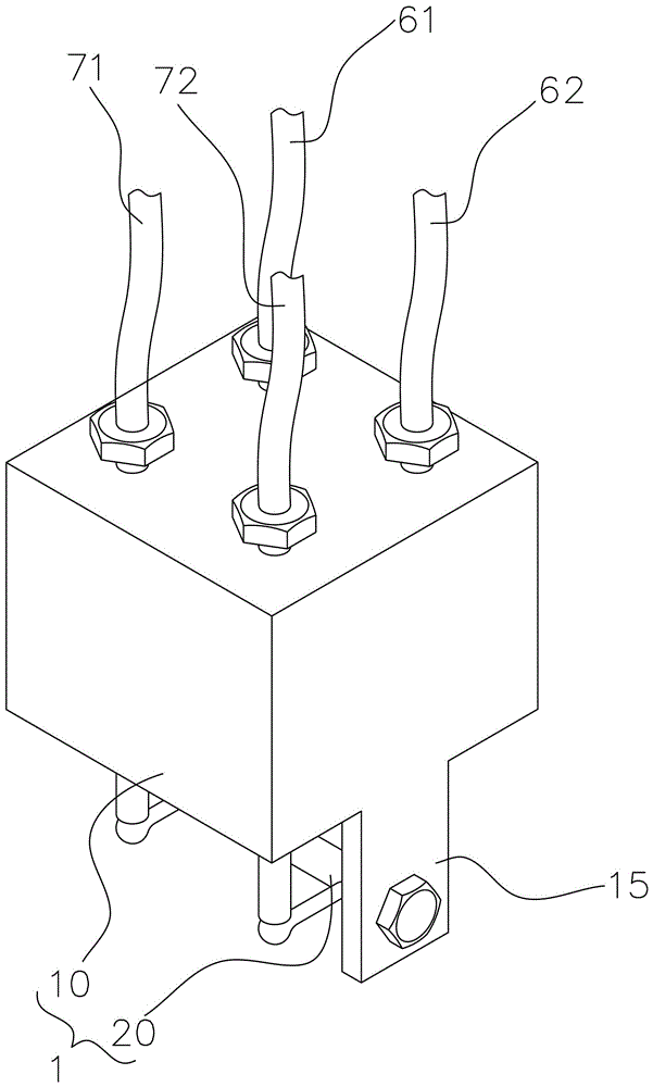
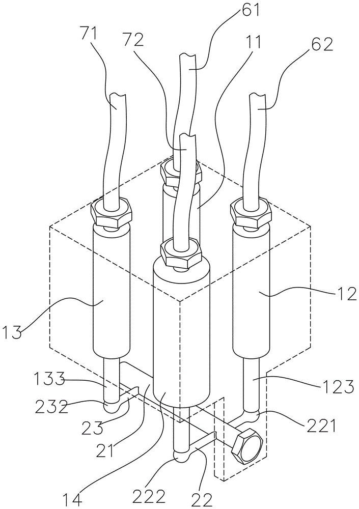
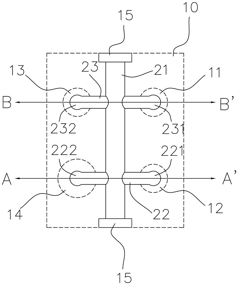
[0061] see Figure 1 to Figure 6 , is a schematic diagram of the first embodiment of the present invention. The hydraulic brake auxiliary device 1 of the present invention is mainly applied to two-wheeled vehicles with hydraulic brakes, such as figure 1 As shown, it can be installed on a two-wheeled vehicle and is connected with the left...


PUM


Abstract

The invention relates to an oil pressure brake auxiliary device, and is mainly applied to brake control of a two-wheel vehicle. The oil pressure brake auxiliary device comprises a body and a transmission mechanism; the body is provided with four cylinder bodies; a slide component is arranged in each cylinder body; one end of the slide component is arranged in the cylinder body, and the other end convexly protrude out of one end of the cylinder body; the slide component can slide in the direction of the cylinder body; the transmission mechanism is combined with the body, and is provided with two driving ends and two interlocking ends; the two driving ends and the two interlocking ends are respectively arranged on the sliding tracks of the four slide components and can be propped against the slide components; when the slide component corresponding to one driving end pushes the driving end, the two interlocking ends are driven to push the corresponding two slide components through the transmission mechanism. When a user conducts brake pressing whether a left brake rod or a right brake rod, the user can conduct brake on the front wheel and the rear wheel; the user can conduct brake action on the front wheel brake device instantly after conducting brake action on the rear wheel brake device, so as to achieve the effect of safe brake.

Description

technical field [0001] The invention relates to a brake auxiliary device, especially for hydraulic two-wheel vehicles, which can control the simultaneous action of front and rear wheel brakes and differentiate the braking force. Background technique [0002] Two-wheeled vehicles, whether bicycles or motor vehicles, have been widely used in human life for a long time. With the development of science and technology, in order to improve the control and sensitivity of brakes more effectively, hydraulic brakes have become Mainstream braking system. [0003] Generally, the braking system of a two-wheeled vehicle uses the brake levers of the left and right handles to control the front and rear brakes respectively, and the friction force between the tire and the ground is used to slow down the speed of the vehicle. When the two-wheeled vehicle is running, the human body will follow the vehicle. Generate an inertial force, often in an emergency situation, the driver accidentally put...

Claims


Application Information

Patent Timeline
Patent Type & Authority Patents(China)
IPC IPC(8): B60T11/10B60T8/26B62L3/08
Inventor 曾东荣
Owner ANSURE
Features
  • Generate Ideas
  • Intellectual Property
  • Life Sciences
  • Materials
  • Tech Scout
  • Unparalleled Data Quality
  • Higher Quality Content
  • 60% Fewer Hallucinations
Learn More