
Apparatus and method for detecting a field of view of a person with a blind spot

A technology of scotoma and field of view, applied in the field of central scotoma, which can solve the problem of uncertainty of the patient's field of vision

Active Publication Date: 2019-09-24
CARL ZEISS VISION INT GMBH
View PDF9 Cites 2 Cited by
  • Summary
  • Abstract
  • Description
  • Claims
  • Application Information

AI Technical Summary

Problems solved by technology

However, the patient's subjectively perceived field of view cannot be determined

Method used


Image

  • Apparatus and method for detecting a field of view of a person with a blind spot
  • Apparatus and method for detecting a field of view of a person with a blind spot
  • Apparatus and method for detecting a field of view of a person with a blind spot

Examples


Embodiment Construction

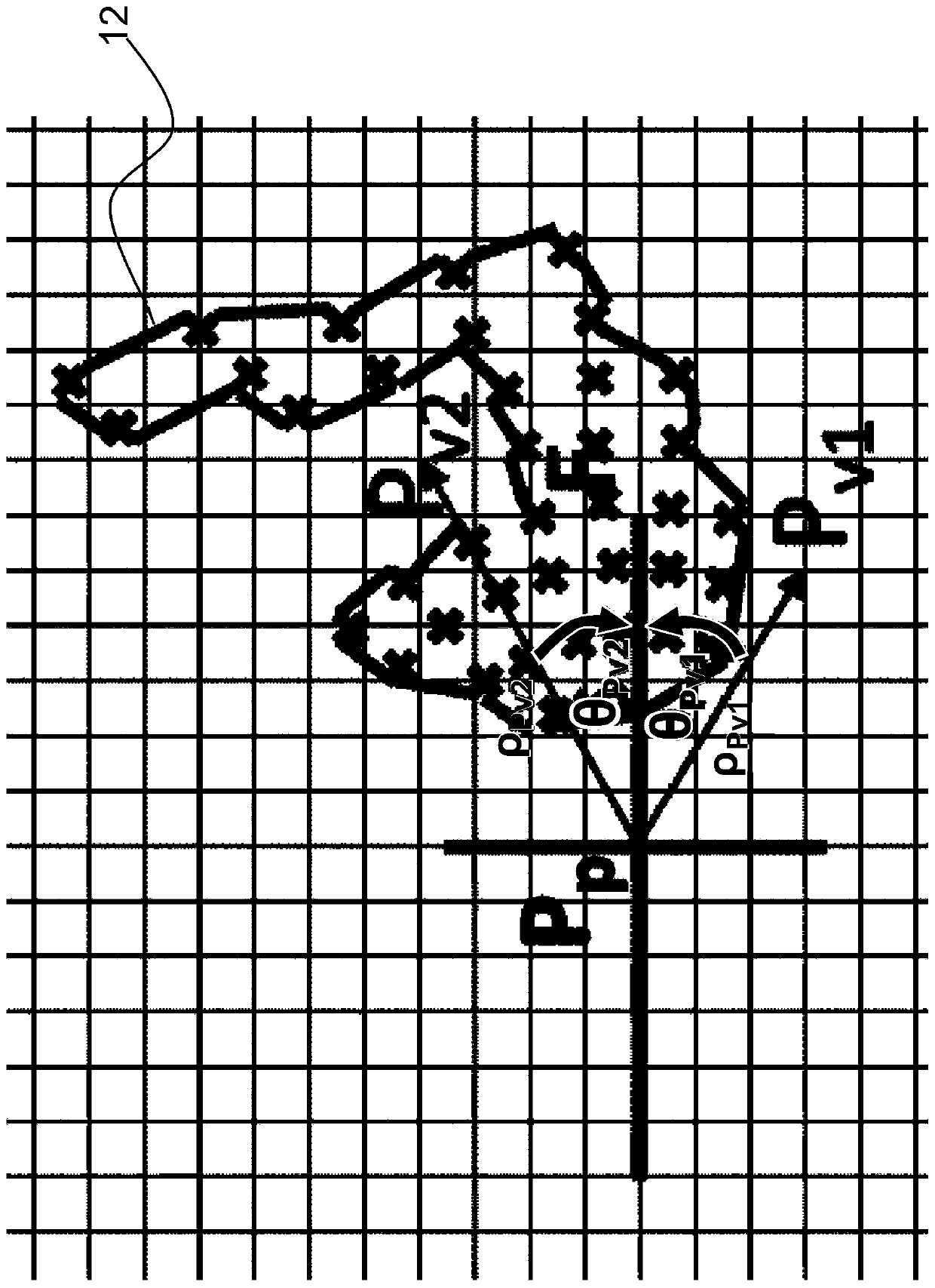
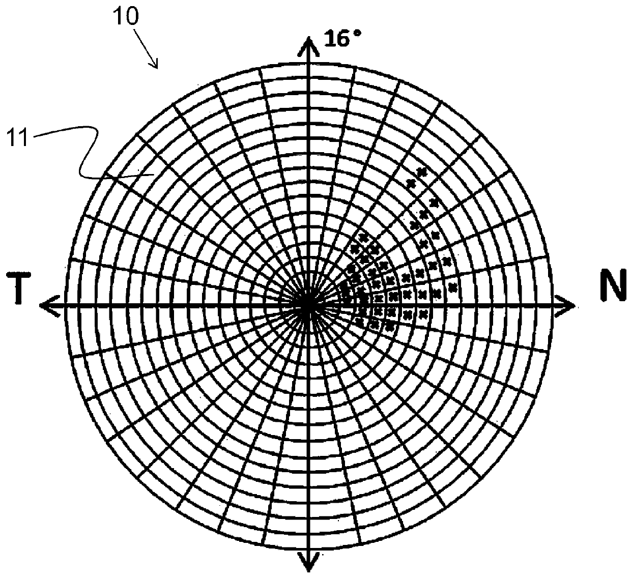
[0102] figure 1 A flowchart for point-by-point sampling of the field of view is shown. Here, the display unit 1 , in particular the screen, is shown at three different successive times A, B and C. The person is instructed to fixate with the left and / or right eye at the point of fixation 2 permanently displayed on the display unit 1 . For example, gaze point 2 is configured as a cross. Furthermore, the sampling point 3 appears on the display unit 1 at time B for a predetermined period of time. By way of example, the sampling point 3 is configured as a circular disk and (its center) is at a distance p from the gaze point 2 and has an angle θ with respect to a line extending preferably horizontally through the gaze point 2 . The gaze point 2 thus defines the origin of a polar coordinate system with this line as the polar axis 4 . The sampling point 3 is located in this polar coordinate system with polar coordinates (ρ, θ). In addition to displaying sampling point 3, the sim...


PUM


Abstract

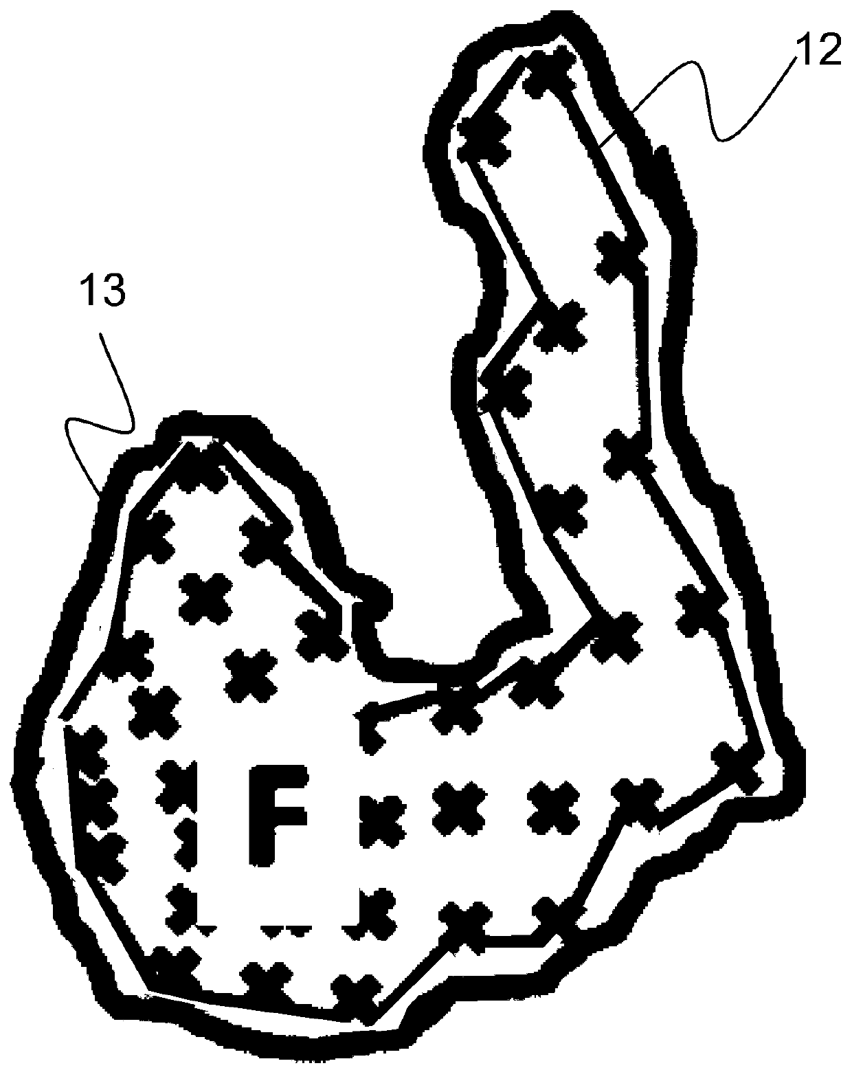
A method and an apparatus for capturing a visual field of a person having a scotoma, in particular a central scotoma, are disclosed. The method includes continuously capturing the eye alignment of the person with a capturing unit, sampling the visual field of the person point-by-point to determine points suitable and not suitable for sight in the visual field of the person, finding the scotoma as a region with a multiplicity of points not suitable for sight, calculating an outer boundary line (12) of the scotoma, calculating an outer enveloping curve (13), which surrounds the outer boundary line (12) of the scotoma at a predetermined distance, and displaying the outer enveloping curve on a display unit (1). The enveloping curve is perceivable by the person on the display unit as a frame of the scotoma.

Description

technical field [0001] The present invention relates to a device and method for capturing the field of vision of a person with a scotoma. Scotomas are parts of the visual field with reduced sensitivity or complete loss (usually due to pathological causes). Scotomas may result from disturbances of the retina, optic tract, and / or visual center. [0002] The invention relates in particular to the central scotoma. Central scotoma involves complete or partial loss of central visual field, ie loss of sensitivity in the macular area, particularly in the fovea area. Background technique [0003] Usually, the loss of central visual field is compensated for by using the remaining healthy areas of the retina. This area is called Prioritized Retinal Locus (PRL) . [0004] It is known that patients do not always form preferential retinal fixation sites in the area that is optimal for a particular visual task. For example, patients often develop a preferential retinal fixation site ...

Claims


Application Information

Patent Timeline
Patent Type & Authority Applications(China)
IPC IPC(8): A61B3/024A61B3/113A61B3/12A61B3/14
CPCA61B3/024A61B3/113A61B3/12A61B3/14A61B3/0025A61B3/0041A61H5/00A61H2201/5064A61H2201/5097A61H2201/50A61B3/0091A61B5/1114
Inventor S.瓦尔K.里法伊M.J.巴拉扎-伯纳尔
Owner CARL ZEISS VISION INT GMBH
Learn More