System and method for side-by-side virtual-real image inspection of devices

A technology of virtual images and live images, which is applied in the fields of optical devices, image enhancement, image analysis, etc., and can solve problems such as difficult inspection and processing, difficult positioning, and complex shapes

Inactive Publication Date: 2015-11-25
SIEMENS AG
View PDF6 Cites 0 Cited by
  • Summary
  • Abstract
  • Description
  • Claims
  • Application Information

AI Technical Summary

Problems solved by technology

[0005] Inspection handling is particularly difficult when the device being inspected is complex
For example, inspecting modern gas turbines with existing inspection systems and methods creates difficulties
One reason for this is that due to the large size of the device and its complex shape, it can be difficult to locate when reviewing video footage of this examination

Method used


Image

  • System and method for side-by-side virtual-real image inspection of devices
  • System and method for side-by-side virtual-real image inspection of devices
  • System and method for side-by-side virtual-real image inspection of devices

Examples


Embodiment Construction

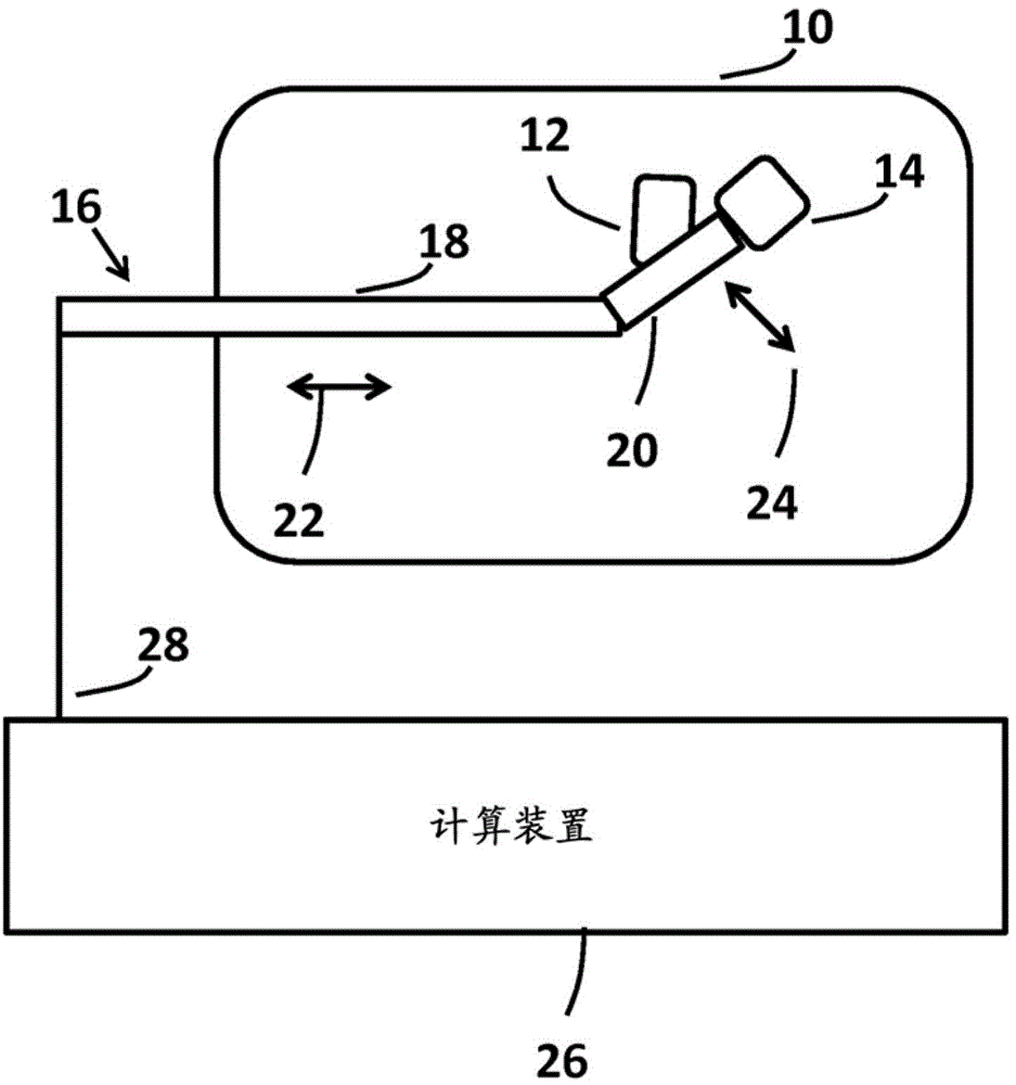
[0027] figure 1 A device under inspection and an inspection system according to an aspect of the present invention are illustrated. The device 10 is shown being inspected. Plant 10 may be any of a number of plants, including turbines, gas turbines, and the like. The inspected device can be quite complex in size as well as in shape. When using a video camera for inspection, it is fairly easy to lose track of where the defect is located. These defects may include damage, cracks, stains, and other defects.

[0028] A plurality of cameras 12, 14 are moved within the inspected device 10 for inspection. The cameras 12 , 14 are mounted on movable, controllable actuators 16 . According to one aspect of the invention, the actuator 16 includes a first arm 18 and a second arm 20 .

[0029] Although two cameras 12, 14 are shown, a single camera could also be used. Alternatively, more than two cameras can also be used.

[0030] The first arm 18 is controllable to move in the direct...


PUM


Abstract

Systems and methods for inspecting a device are disclosed. The method includes arranging the device in a known position relative to a plurality of movable cameras. The plurality of movable cameras are mounted on a controllable actuator. The plurality of cameras are pointed at the device by controlling the controllable actuator to position the camera with a user interface. A computing device renders a virtual image from a CAD model of the device with a computing device. An image of the device generated by the camera is displayed on a display. The computing device also causes the rendered virtual image of the device to be displayed on the display. The camera images and the rendered images can be displayed side-by-side, in an overlay fashion or both.

Description

[0001] Statement of relevant application [0002] This application claims priority to US Patent Provisional Patent Application Serial No. 61 / 386,092 filed September 24, 2010. technical field [0003] The present invention relates to inspection systems and methods using cameras. Background technique [0004] For industrial plants and equipment, computerized inspection based on camera images provides very accurate information. However, inspection becomes difficult if the inspected object is complex (for example, a modern gas turbine), and when multiple cameras and multiple configurations of cameras are involved. It is often not intuitive to imagine the spatial relationship between the individual cameras or camera configurations and the device being inspected. This hampers the productivity of inspection. [0005] The inspection process is particularly difficult when the device to be inspected is complex. For example, inspecting modern gas turbines with existing inspection s...

Claims


Application Information

Patent Timeline
Patent Type & Authority Patents(China)
IPC IPC(8): G01N21/95G01N21/954G01B11/24G01B11/16
CPCG01N21/9515G01B11/245G01N21/954G06T7/001G06T2200/24G06T2207/30164G01B11/16G01B11/24G01N21/95
Inventor 谢炳龙Y.金克高翔
Owner SIEMENS AG
Why Eureka
Try Eureka