
Anti-wear casing pipe for transportation

A kind of anti-wear casing and casing technology, which is applied in the directions of transportation and packaging, railway car body parts, cargo support/fastening parts, etc., and can solve the failure of anti-wear measures, loose rubber anti-wear pads, and rubber anti-wear pads The failure of the anti-loosening flaps and other problems can be achieved to reduce the shear stress and slow down the degree of bending change

Pending Publication Date: 2019-09-24
成都睿智兴华信息技术有限公司
View PDF1 Cites 0 Cited by
  • Summary
  • Abstract
  • Description
  • Claims
  • Application Information

AI Technical Summary

Problems solved by technology

Although the rubber anti-friction pad of this structure can be applied to pulling and binding materials of various diameters such as steel wire ropes, in actual use, due to vibration and other effects, the anti-falling wings on both sides of the rubber anti-friction pad fail, resulting in During the transportation process, Π-shaped and L-shaped rubber anti-wear pads were loose, anti-wear measures failed, and there were violations of direct contact between pulling and binding materials and goods and vehicles at edges and corners

Method used


Image

  • Anti-wear casing pipe for transportation
  • Anti-wear casing pipe for transportation
  • Anti-wear casing pipe for transportation

Examples


Embodiment 1

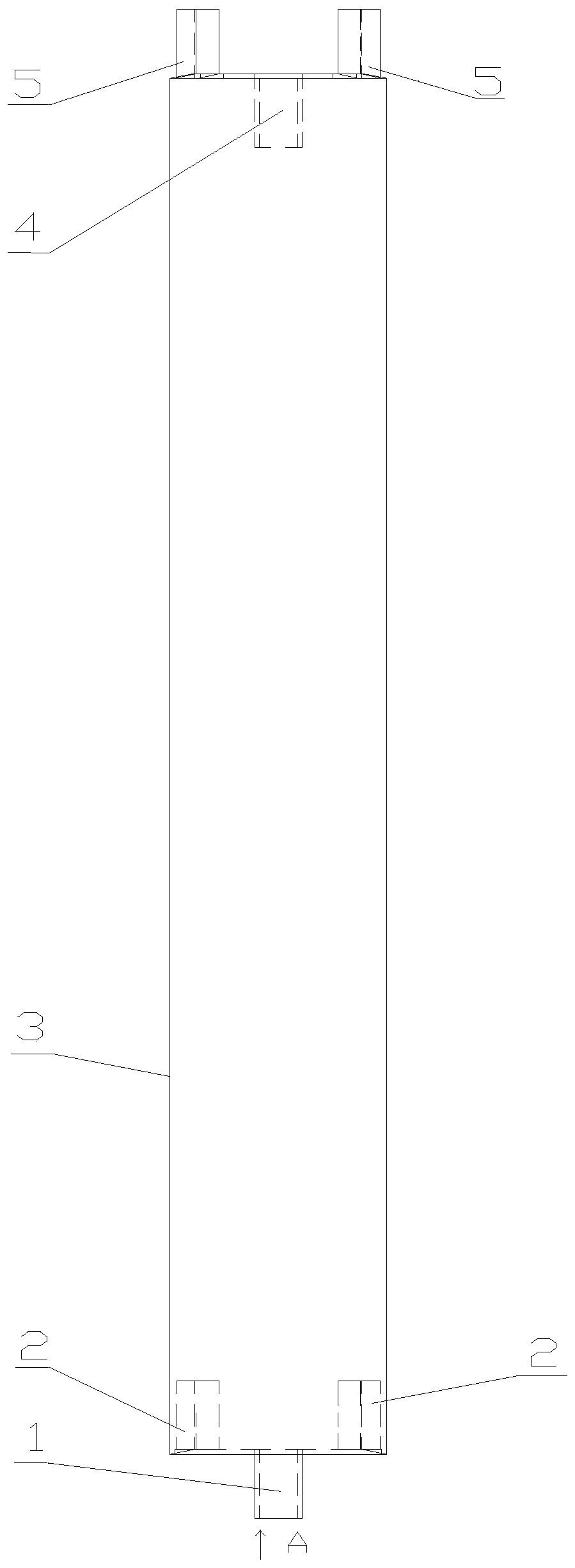
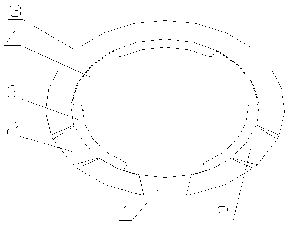
[0027] see figure 1 and figure 2 In this embodiment, mutually parallel longitudinal limiting ribs 6 are arranged on the inner wall of the sleeve body 3 along the length direction of the sleeve, and the groove 7 between any two limiting ribs 6 forms a channel for pulling and binding materials to pass through; Extending structures are provided at both ends of the sleeve body 3 . The extension structure is to set a first convex falcon 1 with a dovetail-shaped cross-sectional shape at the position where one port of the casing body 3 is located in the groove 7, and limit convex falcons located on both sides of the first convex falcon 1 on the inner wall of the same port of the casing body 3. A dovetail groove 2 with a cross-sectional shape is provided on the tube wall on the back of the rib 6, and a dovetail-shaped notch 4 with a dovetail cross-sectional shape is provided at the position where the other port of the casing body 3 is located at the groove 7. Correspondingly, a sec...

Embodiment 2

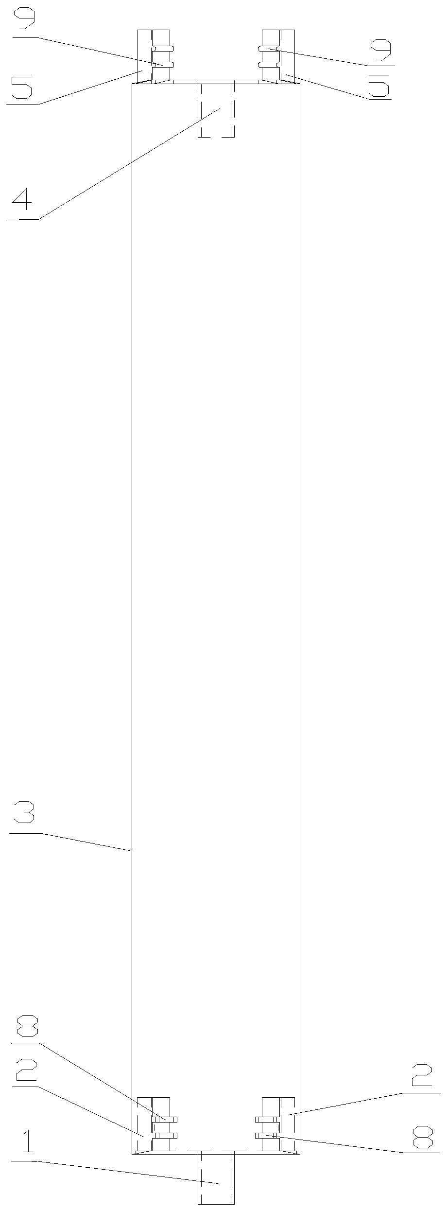
[0030] see image 3 and figure 2 In this embodiment, mutually parallel longitudinal limiting ribs 6 are arranged on the inner wall of the sleeve body 3 along the length direction of the sleeve, and the groove 7 between any two limiting ribs 6 forms a channel for pulling and binding materials to pass through; Extending structures are provided at both ends of the sleeve body 3 . The extension structure is to set a first convex falcon 1 with a dovetail-shaped cross-sectional shape at the position where one port of the casing body 3 is located in the groove 7, and limit convex falcons located on both sides of the first convex falcon 1 on the inner wall of the same port of the casing body 3. A dovetail groove 2 with a cross-sectional shape is provided on the tube wall on the back of the rib 6, and a dovetail-shaped notch 4 with a dovetail cross-sectional shape is provided at the position where the other port of the casing body 3 is located at the groove 7. Correspondingly, a sec...

Embodiment 3

[0034] see Figure 4 , Figure 5 , figure 2 In this embodiment, mutually parallel longitudinal limiting ribs 6 are arranged on the inner wall of the sleeve body 3 along the length direction of the sleeve, and the groove 7 between any two limiting ribs 6 forms a channel for pulling and binding materials to pass through; Extending structures are provided at both ends of the sleeve body 3 . The extension structure is to set a first convex falcon 1 with a dovetail-shaped cross-sectional shape at the position where one port of the casing body 3 is located in the groove 7, and limit convex falcons located on both sides of the first convex falcon 1 on the inner wall of the same port of the casing body 3. A dovetail groove 2 with a cross-sectional shape is provided on the tube wall on the back of the rib 6, and a dovetail-shaped notch 4 with a dovetail cross-sectional shape is provided at the position where the other port of the casing body 3 is located at the groove 7. Correspond...


PUM


Abstract

The invention discloses an anti-wear casing pipe for transportation, relates to the technical field of cargo transportation safety, and particularly discloses an anti-wear member which meets the safety requirements of railway transportation. The anti-wear casing pipe for transportation is characterized in that a limiting element rest is arranged on the inner wall of acasing pipe body, and a groove between two limiting element rests forms a passage; extension structuresare arranged at both ends of the casing pipe body;according to the extension structure, a first convex tennon is arranged on one end opening of the casing pipe body, a tennongroove is formed in each of the pipe wallsof the two sides of the first convex tennon, a notch is formed in the other end opening of the casing pipe body, and a second convex tennon is arranged on each ofthe two sides of the notch. The anti-wear casing pipe for transportation has the beneficial effects that the anti-wear casing pipeis generally of a tubular structure, the method of partially wrapping a pullingholding material is adopted, thereby an anti-wear pad of an ordinary planar structure is effectively prevented from being affected by vibration during the railway transportation,loosening, and failing in anti-wear measures as a result, and uniformity of the anti-wear casing pipe for different shapes of a plurality of"should be taken anti-wear measures" positions is achieved.

Description

technical field [0001] The invention relates to the technical field of cargo transportation safety, in particular to an anti-wear component that meets the safety requirements of railway transportation. Background technique [0002] When loading and transporting goods by railway or road, anti-wear measures should be taken at the corners where the reinforcement line contacts the goods and vehicles. At present, this anti-wear measure is to adopt rubber pads to be placed in the corners of the traction reinforcement material and goods and vehicles. Patent No. 200920304818.7 discloses the "Rubber anti-friction pad for cargo transportation and loading reinforcement", which is divided into models such as Π, C, and L according to the applicable position and shape. Anti-abrasion padding. Although the rubber anti-friction pad of this structure can be applied to pulling and binding materials of various diameters such as steel wire ropes, in actual use, due to vibration and other effec...

Claims


Application Information

Patent Timeline
Patent Type & Authority Applications(China)
IPC IPC(8): B61D45/00
CPCB61D45/00
Inventor 刘运惠张培雯黄健勇席劲松其他发明人请求不公开姓名
Owner 成都睿智兴华信息技术有限公司
Learn More