Supercharge Your Innovation With Domain-Expert AI Agents!

Eccentric oscillating type speed reducing device

A deceleration device and eccentric swinging technology, which is applied to the transmission device, transmission device parts, gear transmission device, etc., can solve the problem of increased processing time, and achieve the effects of good lubricity, inhibition of increase, and suppression of processing time

Active Publication Date: 2019-09-24
SUMITOMO HEAVY IND LTD
View PDF6 Cites 0 Cited by
  • Summary
  • Abstract
  • Description
  • Claims
  • Application Information

AI Technical Summary

Problems solved by technology

[0007] However, in the above-mentioned conventional eccentric oscillating type speed reducer, it is necessary to machine the groove for disposing the above-mentioned solid lubricant in the housing, which causes a problem that the man-hours for machining increase.

Method used


Image

  • Eccentric oscillating type speed reducing device
  • Eccentric oscillating type speed reducing device
  • Eccentric oscillating type speed reducing device

Examples


no. 1 approach

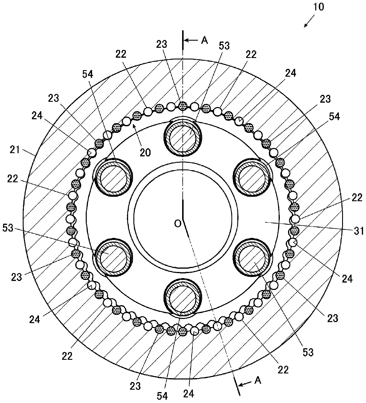
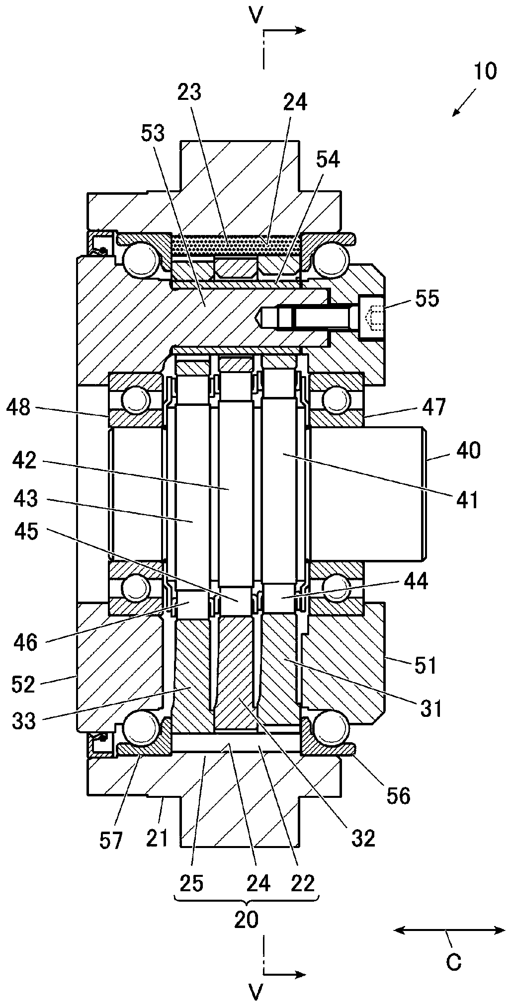
[0021] figure 1 is a cross-sectional view perpendicular to the axial direction C of the eccentric oscillating reduction gear transmission 10 according to the first embodiment of the present invention (along figure 2 The cross-sectional view of the V-V line), figure 2 is along figure 1 A cross-sectional view of the A-O-A line.

[0022] In addition, "the axial direction C" indicates a direction parallel to the center axis of the eccentric body shaft 40 described later of the eccentric oscillating type reduction gear transmission 10 .

[0023] This eccentric oscillating reduction gear 10 has an internal gear 20, a first external gear 31, a second external gear 32, a third external gear 33, an eccentric body shaft 40 integrally having eccentric bodies 41, 42, 43, and is disposed on the first to external gears. The eccentric body bearings 44 , 45 , 46 between the third external gears 31 , 32 , 33 and the eccentric bodies 41 , 42 , 43 , the first carrier 51 , and the second c...


PUM


Abstract

The present invention provides an eccentric oscillating type speed reducing device which improves lubricity. The eccentric oscillating type reduction gear (10) includes an internal gear (20), an external gear (31, 32) that meshes with the internal gear, and an eccentric body (41, 42) that oscillates the external gear, and the internal gear has an internal gear main body (25). a plurality of grooves (24) spaced apart from each other in the circumferential direction of the inner gear main body, and an outer pin (22) rotatably disposed in the groove to constitute the inner teeth, wherein the outer pin is disposed in a part of the plurality of grooves, and at least a portion of the remaining tank is provided with a lubricating member (23) containing a lubricant.

Description

[0001] This application claims priority based on Japanese Patent Application No. 2018-044859 filed on March 13, 2018. The entire contents of this Japanese application are incorporated herein by reference. technical field [0002] The invention relates to an eccentric swing type reduction gear. Background technique [0003] A conventional eccentric oscillating type reduction gear includes: an external gear that eccentrically oscillates through an eccentric body provided on an input shaft; an internal gear that has an external pin as an internal tooth that meshes with the external gear; External gear connection. [0004] The above-mentioned external gear is configured such that the number of teeth is set to be smaller than that of the internal teeth (outer pin) of the internal gear. When the input shaft rotates, the external gear rotates eccentrically and in the direction opposite to the input shaft due to the difference in the number of teeth. The resulting decelerated rota...

Claims


Application Information

Patent Timeline
Patent Type & Authority Applications(China)
IPC IPC(8): F16H1/32
CPCF16H1/32F16H2001/323F16H57/04F16H2001/325F16H2001/327F16H57/0482F16H57/042F16H57/0431
Inventor 金钟刚为永淳西山英彦石川哲三
Owner SUMITOMO HEAVY IND LTD
Features
  • R&D
  • Intellectual Property
  • Life Sciences
  • Materials
  • Tech Scout
  • Unparalleled Data Quality
  • Higher Quality Content
  • 60% Fewer Hallucinations
Learn More