
Electric drive unit with at least two printed circuit boards

A technology for electric drive units and printed circuit boards, which is applied in the direction of electrical components, electric components, and control/drive circuits, and can solve problems such as unrealistic motor sizes

Pending Publication Date: 2019-10-01
ROBERT BOSCH GMBH
View PDF1 Cites 0 Cited by
  • Summary
  • Abstract
  • Description
  • Claims
  • Application Information

AI Technical Summary

Problems solved by technology

Such dimensions of the electric machine are impractical for the restricted installation space in motor vehicles

Method used


Image

  • Electric drive unit with at least two printed circuit boards
  • Electric drive unit with at least two printed circuit boards

Examples


Embodiment Construction

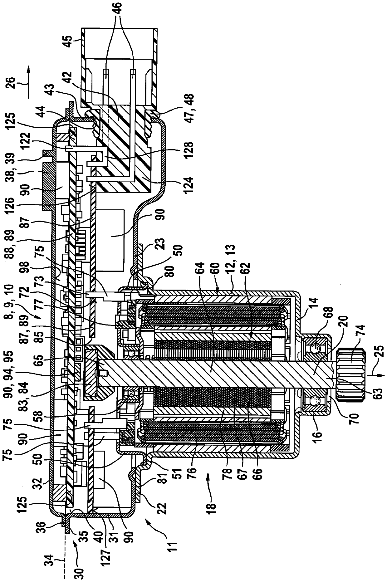
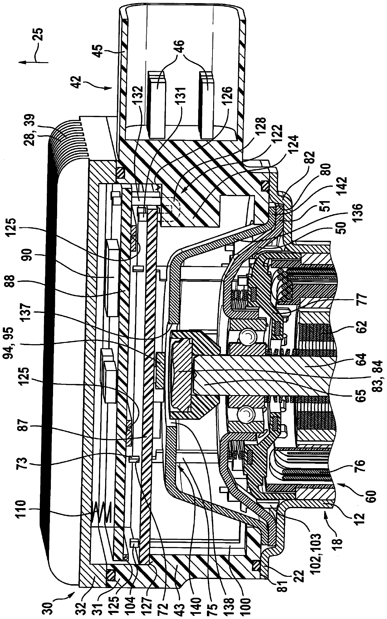
[0020] exist figure 1 An electric drive unit 10 is shown in , which is designed as an electric motor 9 with a housing 11 . Arranged in the pole shell 12 of the housing 11 is a stator 60 which cooperates with a rotor 62 which is arranged on the rotor axis 20 . The rotor 62 has a rotor shaft 64 on which is arranged a rotor body 66 which preferably consists of individual metal laminations. In this exemplary embodiment, the rotor shaft 64 is supported on the base 14 of the pole housing 12 by means of a first bearing 68 . For this purpose, the pole housing 12 has an axial projection 16 which is designed as a bearing seat for a first bearing 68 . The pole housing 12 is designed as a pole pot 13 , which is produced, for example, as a deep-drawn part. The rotor shaft 64 protrudes with a first axial end 63 through an opening 70 of the pole housing 12 in order to transmit the torque of the electric motor 9 to a transmission or a pump or a blower (not shown in detail). In this case, ...


PUM


Abstract

The invention relates to an electric drive unit (10), in particular an electric drive unit for adjusting a movable part in a motor vehicle. The electric drive unit has a housing (11), said housing having a pole housing (12) and an electronic device housing (30) axially connected thereto. The pole housing accommodates a stator (60) and a rotor (62), the electronic device housing accommodates an electronic device unit (89). The electronic device unit (89) has at least two separate, overlapping first and second printed circuit boards (87, 88), wherein the electronic device housing (31) has a connection plug (42), the connection plug has an external contact pin (46), and an electric contact bridge (122) is arranged at the inner side of the connection plug (42) and makes the at least two printed circuit boards (87, 88) to be electrically connected to each other.

Description

technical field [0001] The invention relates to an electric drive unit according to the preambles of the independent claims, which has a pole housing and an electronics housing. Background technique [0002] An electric machine is known from DE 10 2014 206 536 A1, which has a pole pot made of metal. Arranged axially on the pole pot is a plug component made of plastic, on which in turn a cover is arranged which consists of an electrically conductive material. In this case, a printed circuit board is arranged in the plug component, which is surrounded by a shielding plate. The printed circuit board is directly in contact with the pins of the connection plug, which is an integral component of the electronics housing. Since more and more electronic components have to be arranged on the circuit board, the circuit board becomes larger and larger, so that the electronics housing extends radially far beyond the cross section of the pole housing. Such dimensions of the electric ma...

Claims


Application Information

Patent Timeline
Patent Type & Authority Applications(China)
IPC IPC(8): H02K5/22H02K11/30H02K11/33
CPCH02K5/225H02K11/30H02K11/33H02K11/215H02K2211/03H02K11/0141
Inventor H-P.多姆施H.施瓦布
Owner ROBERT BOSCH GMBH
Learn More