
Method and apparatus for estimating a rotation speed of an electric motor

A technology of rotation speed and electric motors, applied to devices using electric/magnetic methods, electronically commutated motor controls, electrical components, etc., can solve problems such as impossible detection of fundamental waves

Active Publication Date: 2010-06-23
ABB (SCHWEIZ) AG
View PDF1 Cites 14 Cited by
  • Summary
  • Abstract
  • Description
  • Claims
  • Application Information

AI Technical Summary

Problems solved by technology

In the case of a synchronous machine, the stator current does not necessarily have a magnetizing component, so at time zero the current vector length is almost zero, and it is impossible to detect the fundamental on this basis

Method used


Image

  • Method and apparatus for estimating a rotation speed of an electric motor
  • Method and apparatus for estimating a rotation speed of an electric motor
  • Method and apparatus for estimating a rotation speed of an electric motor

Examples


Embodiment Construction

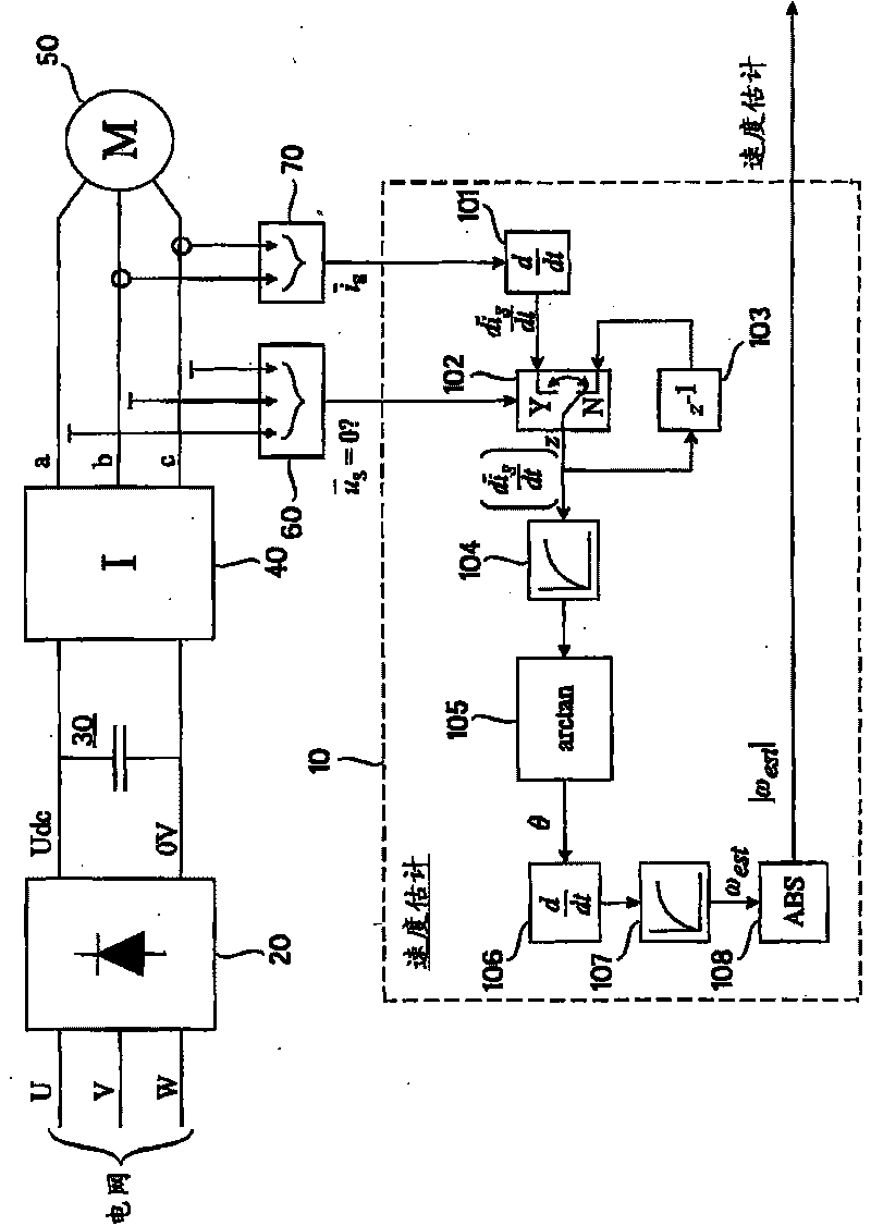
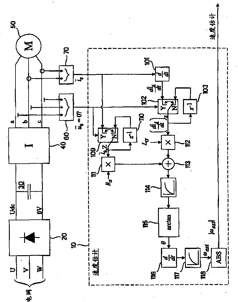
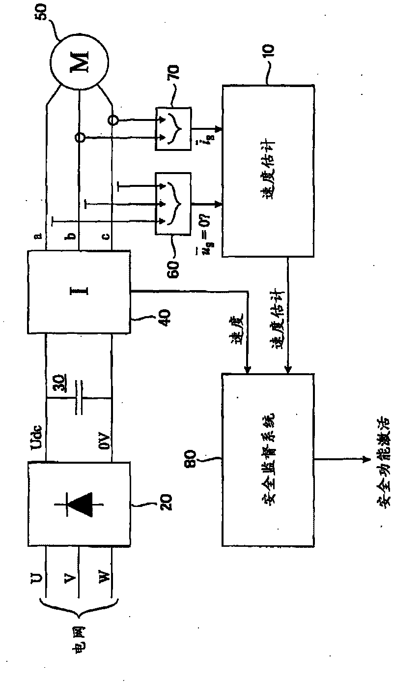
[0015] figure 1 Examples of frequency converter connections shown are described above in the general part of this description and will not be repeated here. It is to be noted that the use of the present invention is not limited to any given type of inverter 40 . The term "inverter" should be broadly understood to cover not only devices having basic inverter functionality, but also devices including suitable control logic for controlling the inverter. The control logic for such an inverter may be implemented within the inverter unit 40 or as a separate unit. The type of power supply U, V, W, 20, 30 of the inverter 40 and the type of connection a, b, c between the inverter 40 and the motor 50, such as their voltage levels, are important to the basic idea of ​​the invention It doesn't matter. The motor 50 may be an asynchronous machine such as an induction motor, or may be a synchronous machine such as a split excitation synchronous motor, a permanent magnet synchronous motor,...


PUM


Abstract

A method and apparatus for estimating a rotation speed of an electric motor supplied by an inverter, the apparatus comprising means (101, 102) for determining a time derivative of a stator current vector of the electric motor (50) during a zero vector state of the inverter (40); and means (104, 105, 106, 107) for determining an estimate of the rotation speed of the electric motor (50) on the basis of the determined time derivative of the stator current vector.

Description

technical field [0001] The present invention relates to the estimation of the rotational speed of an electric motor, and in particular to the estimation of the rotational speed of an inverter powered electric motor. Background technique [0002] An inverter is an electrical device that can be used to supply a load with a voltage having a variable frequency. The inverter is usually used in connection with a frequency converter. figure 1 An example of frequency converter connection is shown. A frequency converter usually consists of two converters, a rectifier 20 and an inverter 40, between which a DC voltage (U dc ) or direct current intermediate circuit 30. The rectifier 20 and the inverter 40 may be located physically separately, and one rectifier may power multiple inverters via a common intermediate circuit 30 . An example of a rectifier 20 is a diode bridge, which is powered from an AC source U, V, W, such as a 50 or 60 Hz AC network (grid), while an example of an in...

Claims


Application Information

Patent Timeline
Patent Type & Authority Applications(China)
IPC IPC(8): G01P3/44
CPCH02P6/182G01P3/44
Inventor 萨穆利·海基莱
Owner ABB (SCHWEIZ) AG
Learn More