Method for operating brake system, and brake system executing same

A braking system, wheel brake technology, applied in the direction of brake transmission, brake, transportation and packaging, etc., can solve the problems of system burst, damage to electromechanical actuators, etc., to achieve the effect of protecting damage

Active Publication Date: 2017-09-26
CONTINENTAL AUTOMOTIVE TECH GMBH
View PDF6 Cites 5 Cited by
  • Summary
  • Abstract
  • Description
  • Claims
  • Application Information

AI Technical Summary

Problems solved by technology

This can create very high back pressures in the system which can lead to damage

Method used


Image

  • Method for operating brake system, and brake system executing same
  • Method for operating brake system, and brake system executing same

Examples


Embodiment Construction

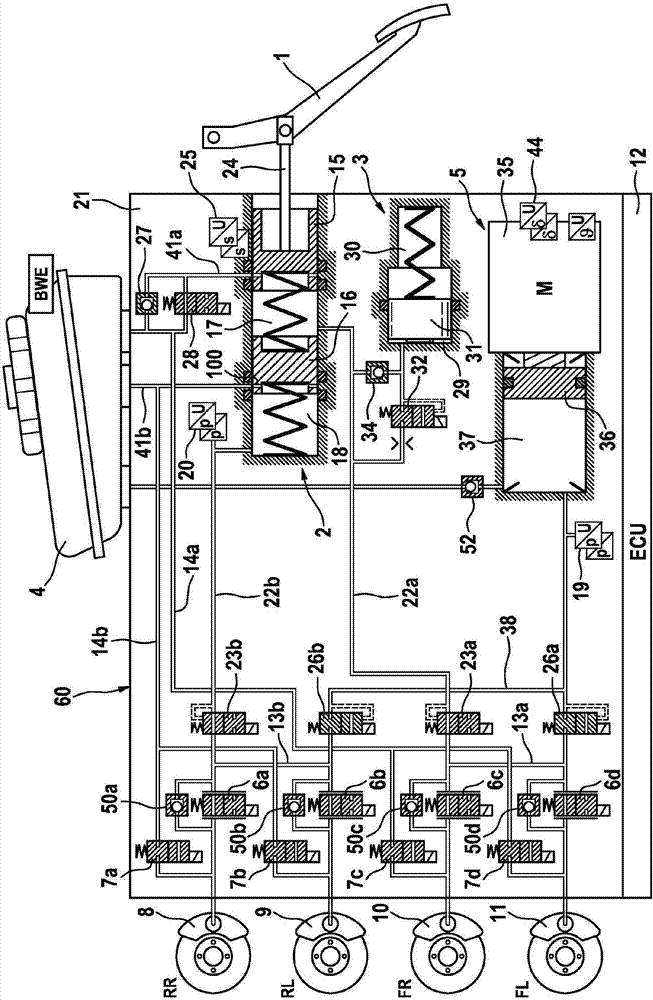
[0034] figure 1 An exemplary embodiment of a braking system for carrying out the method according to the invention is schematically shown in . The brake system basically comprises a brake master cylinder 2 actuatable by means of an operating pedal or brake pedal 1 , an analog device 3 cooperating with the brake master cylinder 2 , pressure medium storage container 4, an electrically controlled pressure supply device 5, an electrically controlled pressure modulation device for adjusting the wheel-dependent brake pressure, and an electronic control and regulation unit 12, said pressure supply device is composed of a hydraulic pressure The chamber 37 is constituted by a cylinder-piston assembly whose piston 36 can be moved by an electromechanical actuator.

[0035]The pressure modulation device, which is not shown in detail, comprises, by way of example, an inlet valve 6 a - 6 d and an outlet valve 7 a - 7 d for each hydraulically actuatable wheel brake 8 , 9 , 10 , 11 of a moto...


PUM


Abstract

The invention relates to a method for operating a brake system for motor vehicles, comprising an electrically controllable pressure supply device (5) which is made of a cylinder/piston arrangement with at least one hydraulic pressure chamber (37), the piston (36) of the arrangement being displaceable by means of an electromechanical actuator (35). The brake system also comprises a number of wheel brakes (8, 9, 10, 11), each of which is connected to the pressure supply device (5) via an electrically actuatable inlet valve (6a-6b), and an electrically actuatable outlet valve (7a-7d) for at least one of the wheel brakes, said wheel brake being connectable to a pressure medium storage container (4) by means of the outlet valve. In a normal control mode (N) of the brake system, a displacement of the piston (36) of the pressure supply device (5) is terminated by outputting an actuation signal to the pressure supply device, and the inlet valves of the wheel brakes are closed in the event of a specified brake condition (A). The normal control mode is switched to a special control mode (S) in the event of a specified condition for the pressure supply device (B). In the event of the specified brake condition (A) in the special control mode, a displacement of the piston (36) of the pressure supply device (5) is terminated by outputting an actuation signal to the pressure supply device, and for at least one selected wheel brake (8, 9), the corresponding inlet valve (6a, 6b) is kept open and the corresponding outlet valve (7a, 7b) is opened at least temporarily while the inlet valves (6c, 6d) of the remaining wheel brakes (10, 11) are closed. The invention also relates to a brake system.

Description

technical field [0001] The invention relates to a method for operating a brake system according to the preamble of claim 1 and a brake system according to the preamble of claim 10 . Background technique [0002] From DE 10 2010 040 097 A1 a "brake-by-wire" braking system for motor vehicles is known, which comprises a tandem brake master cylinder operated by a brake pedal, a brake Simulator of the hydraulic connection of the active master cylinder, an electrically controlled pressure supply device and a pressure modulation device for adjusting the wheel-dependent brake pressure, said pressure supply device consists of a cylinder-piston assembly with a hydraulic pressure chamber, the The piston of the cylinder-piston assembly is displaceable by an electromechanical actuator, and the pressure modulation device has an inlet valve and an outlet valve for each wheel brake. In order to perform normal braking in the "brake-by-wire" operating mode of the brake system, the wheel brak...

Claims


Application Information

Patent Timeline
IPC IPC(8): B60T13/74B60T8/40B60T8/32
CPCB60T8/3275B60T8/4077B60T8/4081B60T13/745B60T13/686B60T13/741B60Y2400/81B60T8/172B60T8/1761B60T8/4054
Inventor D·布克哈特
Owner CONTINENTAL AUTOMOTIVE TECH GMBH
Why Eureka
Try Eureka