Centering clamping device for ceramic thin-wall sleeve part and work method of centering clamping device

A technology of clamping device and thin-walled sleeve, which is applied in the field of mechanical processing of ceramic parts, can solve the problems of irregular inner diameter taper cylinder, difficult to meet the requirements of processing accuracy, and easy deformation, so as to ensure quality, improve rigidity, reduce Effect of tool weight

Active Publication Date: 2019-10-08
山东国晶新材料有限公司
View PDF6 Cites 3 Cited by
  • Summary
  • Abstract
  • Description
  • Claims
  • Application Information

AI Technical Summary

Problems solved by technology

First, because the ceramics are easy to be bumped and cracked or even broken when clamped with a chuck, the product is scrapped
Second, due to the thin wall of the workpiece, it is easy to deform during clamping, making it difficult to meet the machining accuracy requirements
Third, due to the unprocessed inner wall of the workpiece and the irregular cylindrical shape of the inner diameter taper, the traditional mandrel internal support method cannot be clamped, and steel tooling such as static pressure expansion mandrel and plastic mandrel are used when clamping ceramic workpieces. Will cause damage to the inner wall, not applicable
[0003] In the prior art, most of the clamping devices are only for straight cylindrical thin-walled sleeve parts with the same diameter at both ends. Thin-walled sleeve devices are not applicable

Method used


Image

  • Centering clamping device for ceramic thin-wall sleeve part and work method of centering clamping device
  • Centering clamping device for ceramic thin-wall sleeve part and work method of centering clamping device
  • Centering clamping device for ceramic thin-wall sleeve part and work method of centering clamping device

Examples


Embodiment 1

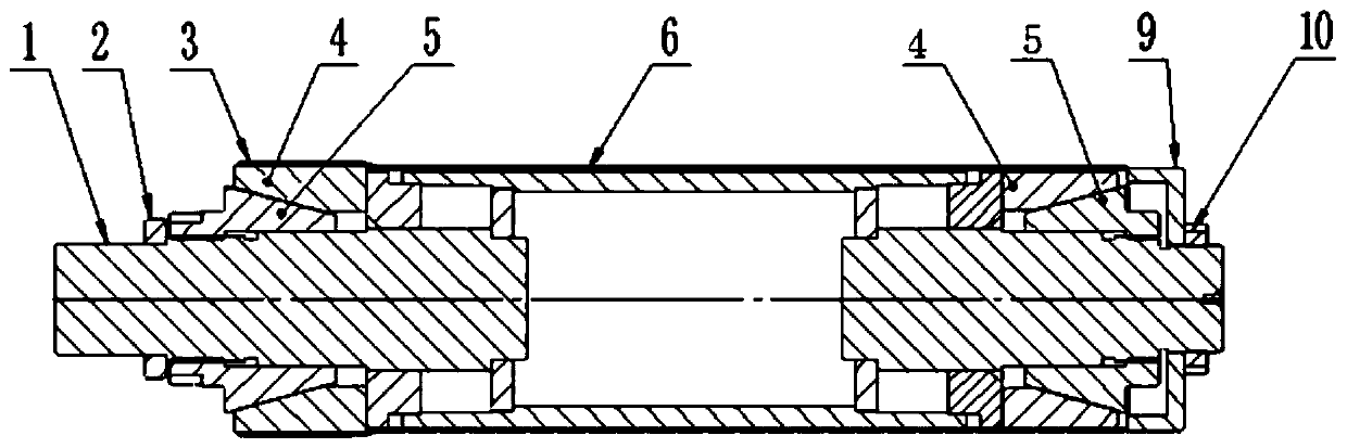
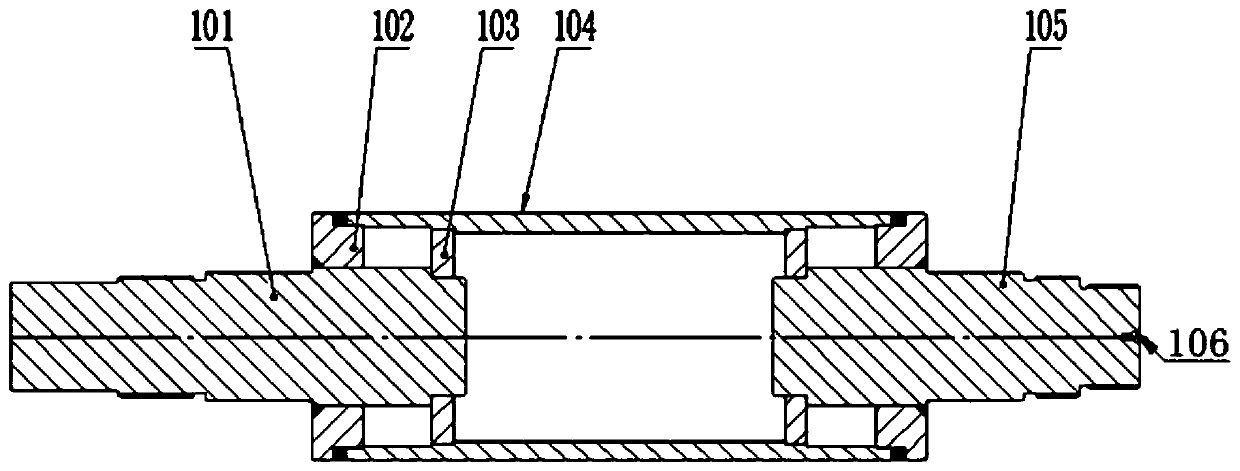
[0038] A centering clamping device for ceramic thin-walled sleeve parts, such as Figure 1~3As shown, it includes a base shaft 1, a movable cone 5 located at both ends of the base shaft 1, and an expansion taper sleeve 4. One end of the base shaft 1 is a clamping shaft 101, the other end is a top shaft 105, and the middle is a cylinder structure 104. The holding shaft 101 and the top shaft 105 are assembled as a whole with the cylinder structure 104 through the end plate 102 and the support plate 103 respectively. The inner diameter of the barrel part 3 is compatible;

[0039] There are two expanding taper sleeves 4 and two moving cones 5, and one expanding taper sleeve 4 and one moving cone 5 are sequentially set on the clamping shaft 101 and the top shaft 105, and the moving cone 5 passes through Threaded on the clamping shaft 101 and the top shaft 105, the expansion taper sleeve 4 is close to the end plate 102 of the base shaft, and the expansion taper sleeve 4 is provided...

Embodiment 2

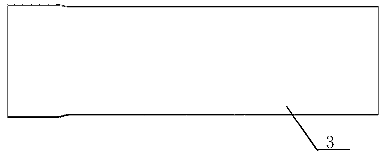
[0044] A centering and clamping device for ceramic thin-walled sleeve parts, the structure of which is shown in Embodiment 1, the difference is that the diameters of the two ends of the ceramic thin-walled sleeve part 3 are different, and the inner diameter and outer diameter are different, respectively. part and the large diameter part, the outer diameter of the barrel structure 104 is adapted to the inner diameter of the small diameter part of the ceramic thin-walled sleeve part. The ceramic thin-walled sleeve parts with different inner diameters at both ends of the present invention are mainly used in solar thin film preparation heating systems. The large-diameter part is required by the assembly structure, and the small-diameter part is the heating area. The total length of the ceramic thin-walled sleeve parts 360-400mm, the diameter of the large diameter part is 120-124mm, and the diameter of the small diameter part is 116-120mm.

Embodiment 3

[0046] A centering clamping device for ceramic thin-walled sleeve parts, the structure of which is shown in Embodiment 2, the difference is that a plurality of shoulders are arranged on the clamping shaft 101, and the clamping shaft is divided into two parts from the inside to the outside. There are sections A, section B and section C whose diameters decrease in order, and a plurality of shoulders are also arranged on the top shaft 105, and the top shaft 105 is divided into sections D, section D, and section Section E and section F;

[0047] Two expansion taper sleeves 4 are respectively arranged on section A and section D, and two moving cones 5 are respectively threaded on section B and section E, and both of them pass through the second cone surface and the expansion taper sleeve 4 to match the first taper surface;

[0048] Section C is provided with a stopper 2, the inner hole of the stopper 2 is a clearance fit with the clamping shaft 101, the base shaft 1 forms an axial...


PUM


Abstract

The invention relates to a centering clamping device for a ceramic thin-wall sleeve part and a work method of the centering clamping device and belongs to the field of ceramic part machining. The centering clamping device comprises a base body shaft, movable cones and expansion cone sleeves, wherein the movable cones and the expansion cone sleeves are located at the two ends of the base body shaft, the number of the expansion cone sleeves is two, and the number of the movable cones is two. A clamping shaft is sequentially sleeved with one expansion cone sleeve and one movable cone, and an ejection shaft is sequentially sleeved with one expansion cone sleeve and one movable cone. The movable cones are in threaded connection to the clamping shaft and the ejection shaft, the expansion cone sleeves are close to end plates of the base body shaft, the expansion cone sleeves are provided with first cone faces inclined towards the movable cones, the movable cones are provided with second conefaces, and the movable cones at the two ends are screwed so that the expansion cone sleeves can be extruded to achieve the expansion action. A center hole is formed in the end portion of the ejectionshaft. A soft body material is arranged on the outer surface of a cylinder structure, and a clearance exists between the soft body material and the inner wall of the ceramic thin-wall sleeve part. Thedevice is small in weight, the cost is reduced, and the inner surface of an inner hole is not damaged; and the centering clamping device can be applied to ceramic thin-wall sleeve parts with different inner diameters at the two ends.

Description

technical field [0001] The invention relates to a centering and clamping device for ceramic thin-walled sleeve parts and a working method thereof, belonging to the technical field of ceramic parts machining. Background technique [0002] Ceramic thin-walled sleeve parts need to support the inner hole to achieve clamping when processing the outer circle. First, because the ceramics are easy to be bumped and cracked or even broken when clamped with a chuck, the product is scrapped. Second, due to the thin wall of the workpiece, it is easy to deform during clamping, which makes it difficult to meet the requirements for machining accuracy. Third, due to the unprocessed inner wall of the workpiece and the irregular cylindrical shape of the inner diameter taper, the traditional mandrel internal support method cannot be clamped, and steel tooling such as static pressure expansion mandrel and plastic mandrel are used when clamping ceramic workpieces. Will cause damage to the inner...

Claims


Application Information

Patent Timeline
Patent Type & Authority Applications(China)
IPC IPC(8): B24B41/06
CPCB24B41/067
Inventor 刘汝强王殿春刘庆毅赵旭荣吴思华
Owner 山东国晶新材料有限公司
Why Eureka
Try Eureka