Supercharge Your Innovation With Domain-Expert AI Agents!

Accelerator shaft-installing pre-locating mechanism

A front positioning and accelerator technology, applied in workpiece clamping devices, manufacturing tools, etc., can solve the problems of heavy labor, inability to guarantee the movement of the connecting rod, and difficulty in ensuring the connecting rod and the base, so as to reduce labor intensity and improve The effect of production efficiency

Pending Publication Date: 2019-10-08
南京博士朗新能源科技有限公司
View PDF0 Cites 0 Cited by
  • Summary
  • Abstract
  • Description
  • Claims
  • Application Information

AI Technical Summary

Problems solved by technology

[0002] The throttle needs to adjust the connecting rod and base to a specific position when installing the shaft sleeve and shaft, but before installing the shaft and shaft sleeve, a spring needs to be installed on the throttle, as attached Figure 7 For the accelerator shown in the figure, after the spring is installed, there is an elastic force along the axial direction of the spring, which cannot guarantee the movement of the connecting rod along a certain rotating shaft on the base. Before the sleeve and shaft are installed, the connecting rod and the base have been connected through a rotating shaft. Therefore, it is difficult to ensure that the connecting rod and the base are in a specific position. The current solution still relies on manual forced pressing, but the labor load of workers is very large when mass production.

Method used


Image

  • Accelerator shaft-installing pre-locating mechanism
  • Accelerator shaft-installing pre-locating mechanism
  • Accelerator shaft-installing pre-locating mechanism

Examples


Embodiment

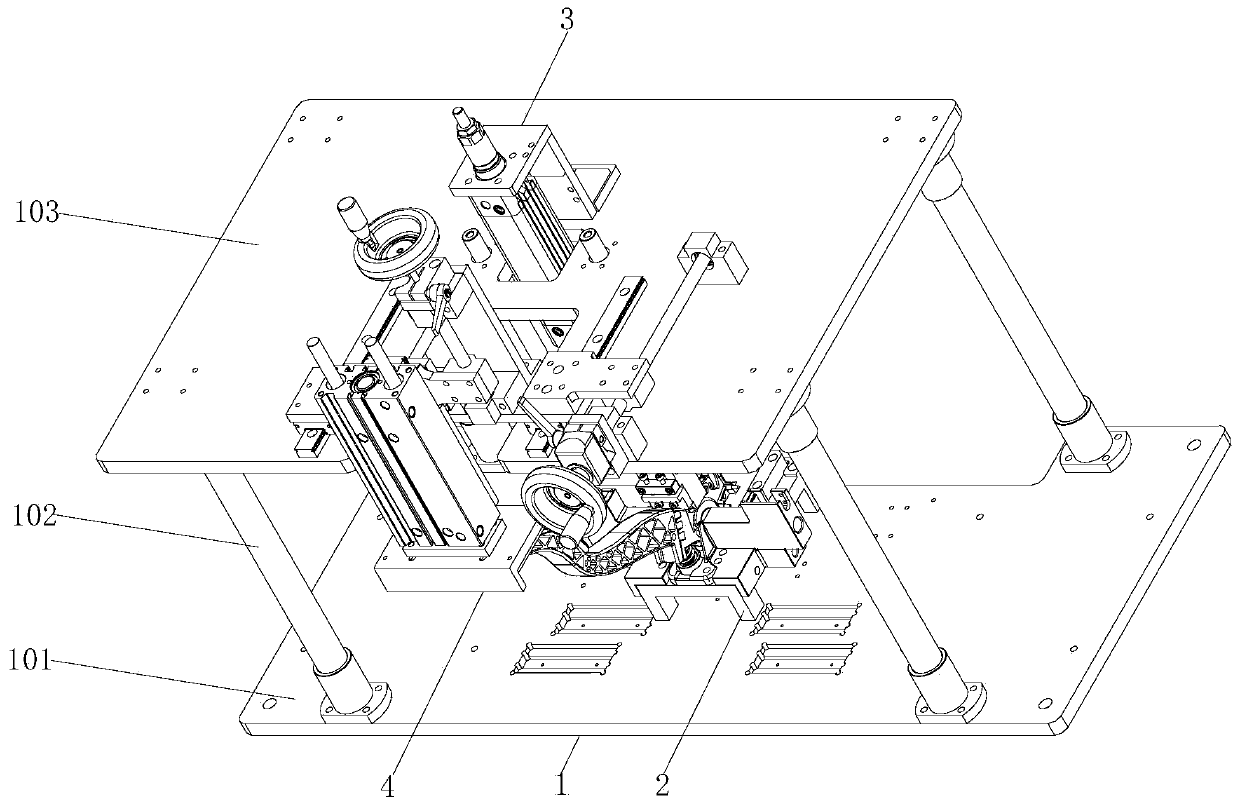
[0027] see Figure 1-7 , the present invention provides the following technical solutions: a positioning mechanism before the throttle shaft is installed, including a bracket mechanism 1, a base mechanism 2, a connecting rod fine positioning mechanism 3 and a connecting rod rough positioning mechanism 4, a base mechanism 2, a connecting rod fine positioning mechanism Both the mechanism 3 and the connecting rod rough positioning mechanism 4 are fixed on the bracket mechanism 1 .

[0028] The support mechanism 1 includes a bottom plate 101 , four pillars 102 are fixedly installed on the top of the bottom plate 101 , and a top plate 103 is fixedly installed on the top of the four pillars 102 .

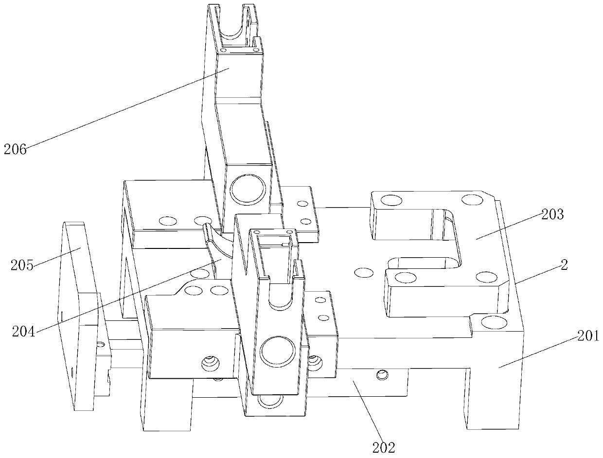
[0029] The abutment mechanism 2 includes a base plate 201 and an end face positioning cylinder 202. An end face positioning plate 203, a guide block 204 and two feed blocks 206 are fixedly installed on the top of the base plate 201, and an end face pressing plate is fixedly installed on t...


PUM


Abstract

The invention belongs to the technical field of accelerator assembling locating equipment and particularly provides an accelerator shaft-installing pre-locating mechanism. The accelerator shaft-installing pre-locating mechanism comprises a support mechanism, a base station mechanism, a connecting rod fine locating mechanism and a connecting rod rough locating mechanism. The base station mechanism,the connecting rod fine locating mechanism and the connecting rod rough locating mechanism are fixed to the support mechanism correspondingly. The support mechanism comprises a baseplate. Four support columns are fixedly installed on the top of the baseplate. According to the accelerator shaft-installing pre-locating mechanism, through cooperation of the base station mechanism, the connecting rodfine locating mechanism and the connecting rod rough locating mechanism, the base station mechanism is utilized firstly so that the position of the base can be fixed; and then a connecting rod is driven to rotate through the connecting rod fine locating mechanism and the connecting rod rough locating mechanism, and thus the connecting rod and the base are adjusted to specific positions. Comparedwith existing manual pressing, labor intensity of workers is lowered; production efficiency of accelerators can be improved; the mechanism is applicable to production of large-scale accelerators; a mechanized manner is adopted to adjust positions of the connecting rod and the base; and the mechanism is more convenient and swift.

Description

technical field [0001] The invention relates to the technical field of throttle assembly and positioning equipment, in particular to a positioning mechanism before the throttle shaft is installed. Background technique [0002] The throttle needs to adjust the connecting rod and base to a specific position when installing the shaft sleeve and shaft, but before installing the shaft and shaft sleeve, a spring needs to be installed on the throttle, as attached Figure 7 For the accelerator shown in the figure, after the spring is installed, there is an elastic force along the axial direction of the spring, which cannot guarantee the movement of the connecting rod along a certain rotating shaft on the base. Before the sleeve and shaft are installed, the connecting rod and the base have been connected through a rotating shaft. Therefore, it is difficult to ensure that the connecting rod and the base are in a specific position. The current solution still relies on manual forced pres...

Claims


Application Information

Patent Timeline
Patent Type & Authority Applications(China)
IPC IPC(8): B25B11/02
CPCB25B11/02
Inventor 陈武宏王巧根
Owner 南京博士朗新能源科技有限公司
Features
  • R&D
  • Intellectual Property
  • Life Sciences
  • Materials
  • Tech Scout
  • Unparalleled Data Quality
  • Higher Quality Content
  • 60% Fewer Hallucinations
Learn More