Rotor engine wearing detecting device and method

A technology of a rotary engine and a detection device, applied in the detection field, can solve the problems of staying in numerical simulation, unable to understand the wear situation intuitively and accurately, and achieve the effects of convenient and accurate collection, simple and fast detection process, and simple structure

Inactive Publication Date: 2019-10-08
NORTHWESTERN POLYTECHNICAL UNIV
View PDF10 Cites 5 Cited by
  • Summary
  • Abstract
  • Description
  • Claims
  • Application Information

AI Technical Summary

Benefits of technology

This patented technology helps detect damage caused by wearing out parts inside an internal combustion machine's pistons or valves when they start up again after being used for some time without stopping working properly. By analyzing this data with certain techniques, it becomes possible to identify any areas where there may have been damages beforehand. Overall, these technical improvements make engines more reliable over their lifespan while still maintain good performance even if worn beyond expected levels.

Problems solved by technology

Technological Problem: Rotational engines have unique features that make them difficult to use effectively at very fast speeds or during extreme temperatures due to their small dimensions. These machines are subjected to severe environmental factors such as air pollution from exhaust gases emitted by combustion processes inside these devices. Additionally, they often operate over prolonged periods without maintenance because of its design and materials properties. Overall, this problem poses challenges when studying how well the machine works properly while still being able to keep up enough oil supply to prevent excessive heat buildup caused by poor lubrications.

Method used


Image

  • Rotor engine wearing detecting device and method
  • Rotor engine wearing detecting device and method
  • Rotor engine wearing detecting device and method

Examples


Embodiment Construction

[0031] Example embodiments will now be described more fully with reference to the accompanying drawings. Example embodiments may, however, be embodied in many forms and should not be construed as limited to the embodiments set forth herein; rather, these embodiments are provided so that this disclosure will be thorough and complete, and will fully convey the concept of example embodiments to those skilled in the art. The same reference numerals in the drawings denote the same or similar structures, and thus their detailed descriptions will be omitted.

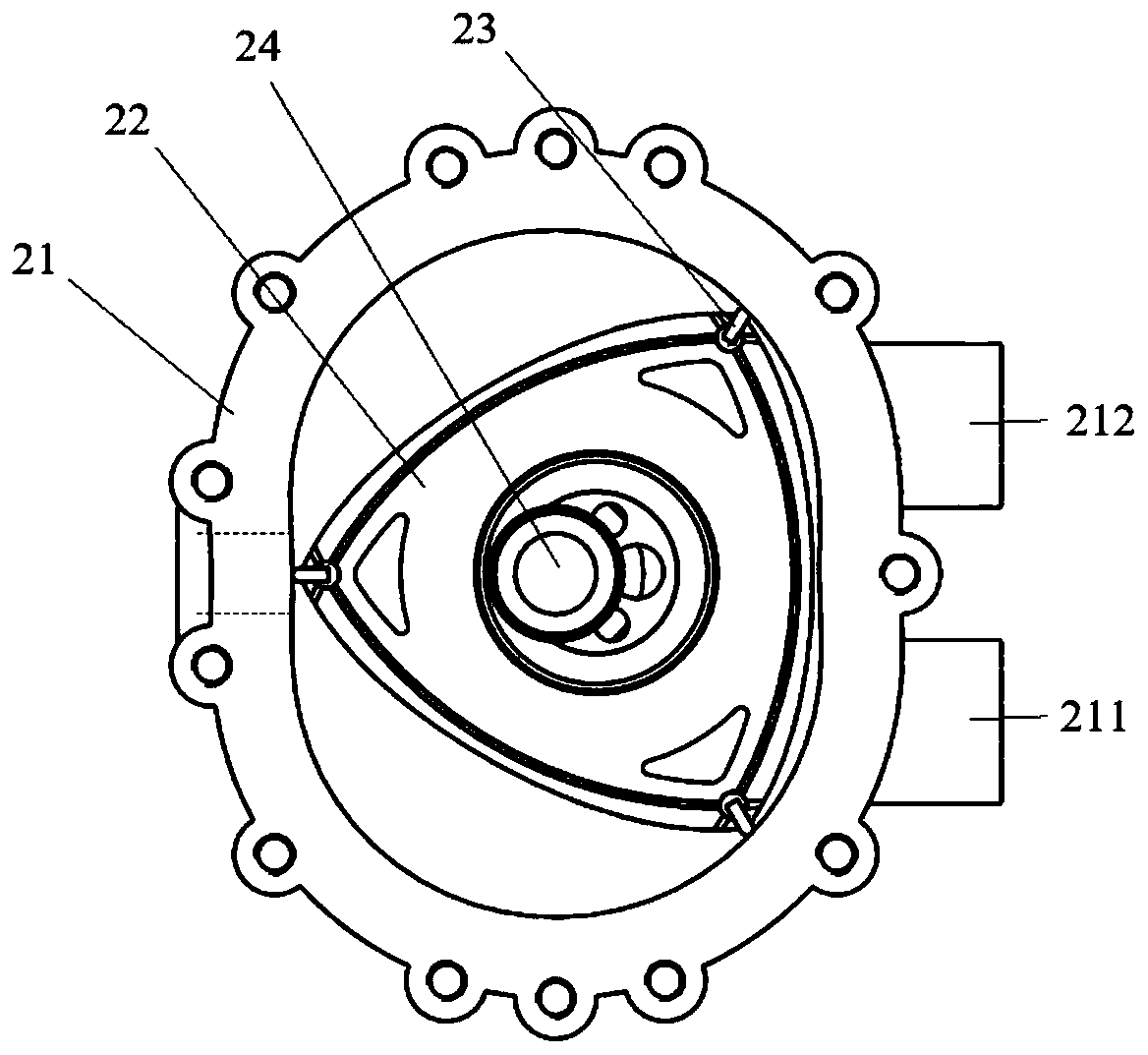
[0032] The structure of the rotary engine is as figure 1 As shown, the apex of the triangular rotor 22 is in surface contact with the cylinder 21, thereby forming three independent air chambers in the cylinder 21. The rotor 22 is constantly moving around the combustion chamber, and the three volumes of gas alternately expand and contract. It is this expansion and contraction that draws air and fuel into the engine through in...


PUM


Abstract

The invention provides a rotor engine wearing detecting device and method. The detecting device comprises a driver and a magnetic barrier, the driver is used to drive a rotor engine to rotate, the magnetic barrier is arranged in a cylinder of the rotor engine and used to absorb chips due to wearing in the cylinder in the rotation process of the engine rotor, and further the wearing condition can be analyzed according to the collected chips. The detecting device can simulate the practical operation condition of the rotor engine, the wearing chips can be collected conveniently and accurately, and help is provided for further fine analysis. The whole detection process is simple and rapid, the structure is simple, and the device and method are easy to realize.

Description


Claims


Application Information

Patent Timeline
Owner NORTHWESTERN POLYTECHNICAL UNIV
Why Eureka
Try Eureka