
Lamp panel assembly and display device

A technology for light panels and components, applied in the field of light panel components and display devices, can solve the problems of warping at splicing, affecting display, uneven light mixing, etc., and achieve the effects of reducing gaps, improving stability, and improving uneven brightness

Inactive Publication Date: 2019-10-11
WUHAN CHINA STAR OPTOELECTRONICS TECH CO LTD
View PDF15 Cites 7 Cited by
  • Summary
  • Abstract
  • Description
  • Claims
  • Application Information

AI Technical Summary

Problems solved by technology

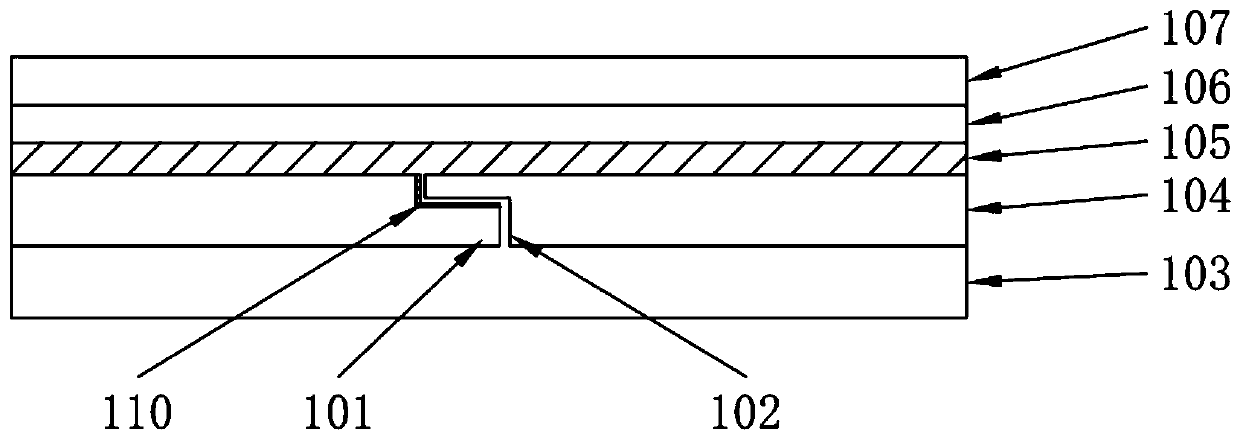
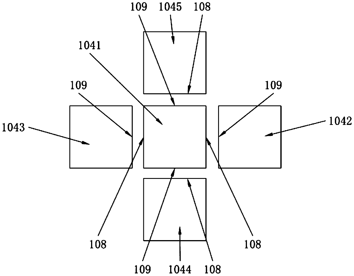
[0005] The invention provides a lamp panel assembly and a display device. By setting a more stable lamp panel splicing structure, the gap at the splicing part of the lamp panel is reduced, thereby solving the problem of warpage, breakage, etc. The defect of uneven light mixing, which in turn affects the technical problems of display

Method used


Image

  • Lamp panel assembly and display device
  • Lamp panel assembly and display device
  • Lamp panel assembly and display device

Examples


Embodiment Construction

[0027] The following descriptions of the various embodiments refer to the accompanying drawings to illustrate specific embodiments in which the invention may be practiced. The directional terms mentioned in the present invention, such as [top], [bottom], [front], [back], [left], [right], [inside], [outside], [side], etc., are only for reference The orientation of the attached schema. Therefore, the directional terms used are used to illustrate and understand the present invention, but not to limit the present invention. In the figures, structurally similar elements are denoted by the same reference numerals.

[0028] The present invention aims at the defects of the existing lamp panel assembly, such as warping, breakage and uneven light mixing at the splicing part due to the instability of the gap at the splicing part of the lamp board, and this embodiment can solve the defects.

[0029] The present invention provides a lamp panel assembly. The lamp panel assembly includes a...


PUM


Abstract

The invention discloses a lamp panel assembly and a display device. The lamp panel assembly comprises a plurality of mutually-spliced lamp panels, and a connecting part is formed between any two adjacent lamp panels; and each connecting part comprises a convex part and a concave part, wherein the convex part and the concave part are arranged on the two corresponding adjacent lamp panels correspondingly and mutually embedded. By arranging the convex parts and the concave parts which can be stably connected on the spliced positions of the lamp panels, the splicing stability of the lamp panels isimproved, gaps in the spliced positions of the lamp panels are reduced, and the phenomenon of the uneven brightness of the lamp panels is improved.

Description

technical field [0001] The invention relates to the field of display technology, in particular to a lamp panel assembly and a display device. Background technique [0002] As a backlight source, Mini LED has a larger number of LEDs, but is smaller than the currently used LEDs, enabling thinner displays and improved local contrast. It meets the industry's requirements for high contrast and brightness, and curved surface fit. and durability requirements. [0003] For medium and large-sized mini LED boards, it can only be achieved by splicing multiple pieces, but there are the following problems: warping of the splicing, uneven splicing, breakage of the splicing, light cutoff, dark lines caused by cutting black edges at the splicing Appear. [0004] At present, a large OD (optic distance, mixed light space) is usually used to cover, but as the thickness of the light board becomes thinner and thinner, the reserved OD is also more limited, making the seam of the light board spl...

Claims


Application Information

Patent Timeline
Patent Type & Authority Applications(China)
IPC IPC(8): G09F9/00
CPCG09F9/00
Inventor 刘凡成
Owner WUHAN CHINA STAR OPTOELECTRONICS TECH CO LTD
Learn More