Eureka AIR delivers breakthrough ideas for toughest innovation challenges, trusted by R&D personnel around the world.

Power transformer hot spot temperature rise calculating method, system and device and storage medium

A technology of power transformers and calculation methods, applied in computer-aided design, calculation, instruments, etc., can solve the problems of low accuracy, reduce the accuracy of hot spot temperature rise, and low accuracy of convective heat transfer coefficient, so as to improve accuracy and improve The effect of computational precision

Inactive Publication Date: 2019-10-15
HANGZHOU ELECTRIC EQUIP MFG +2
View PDF6 Cites 3 Cited by
  • Summary
  • Abstract
  • Description
  • Claims
  • Application Information

AI Technical Summary

Problems solved by technology

When predicting the convective heat transfer coefficient, the empirical formula is usually used for simple and rough calculations. Due to the complexity of the oil flow inside the power transformer, the accuracy of the convective heat transfer coefficient determined in the traditional scheme is low.
Since the method of determining the electromagnetic stray loss and convective heat transfer coefficient is relatively simple, the accuracy is low, which will reduce the accuracy of the calculated hot spot temperature rise, which is not conducive to the stable operation of the transformer and the guarantee of the life of the transformer.

Method used


Image

  • Power transformer hot spot temperature rise calculating method, system and device and storage medium
  • Power transformer hot spot temperature rise calculating method, system and device and storage medium
  • Power transformer hot spot temperature rise calculating method, system and device and storage medium

Examples


Embodiment Construction

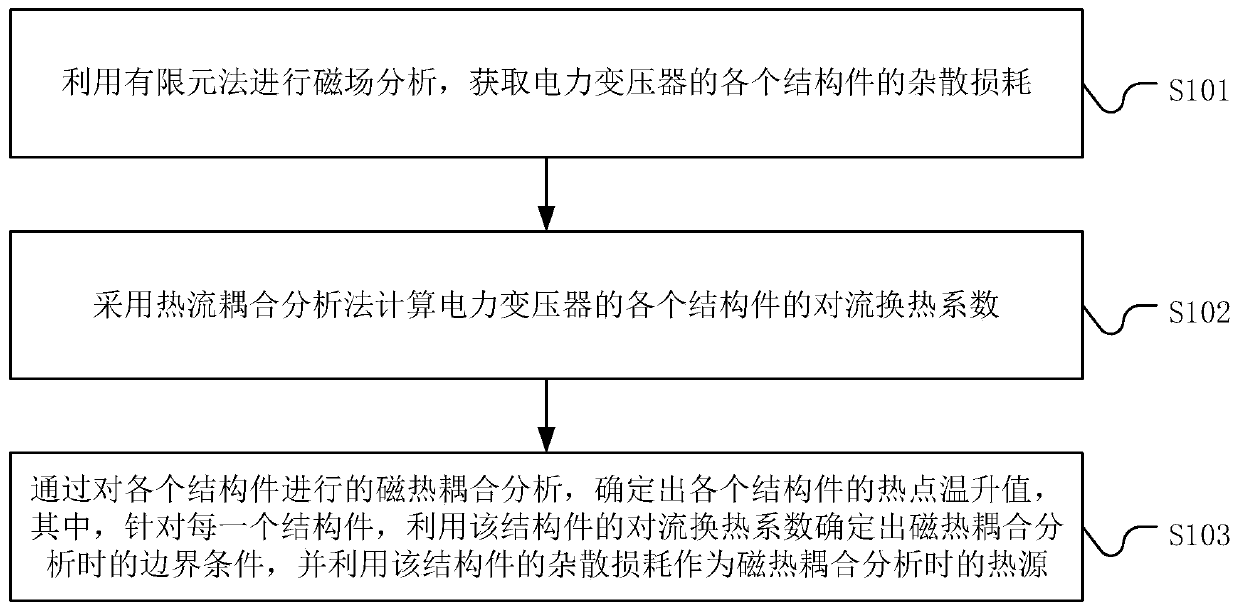
[0053] The core of the present invention is to provide a method for calculating the temperature rise of the hot spot of a power transformer. The solution of the application is beneficial to improving the calculation accuracy of the temperature rise of the hot spot of the power transformer.

[0054] In order to enable those skilled in the art to better understand the solution of the present invention, the present invention will be further described in detail below in conjunction with the accompanying drawings and specific embodiments. Apparently, the described embodiments are only some of the embodiments of the present invention, but not all of them. Based on the embodiments of the present invention, all other embodiments obtained by persons of ordinary skill in the art without making creative efforts belong to the protection scope of the present invention.

[0055] Please refer to figure 1 , figure 1 It is an implementation flowchart of a calculation method for a power trans...


PUM


Abstract

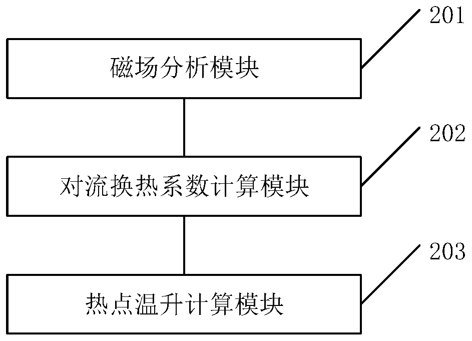
The invention discloses a power transformer hot spot temperature rise calculating method. The method comprises the following steps of using a finite element method to carry out magnetic field analysis, thus obtaining stray losses of each structural member of a power transformer; calculating a convective heat transfer coefficient of each structural member of the power transformer by adopting a heatflow coupling analysis method; according to the method, the hot spot temperature rise value of each structural member is determined through magneto-thermal coupling analysis on each structural member, for each structural member, the boundary condition during magneto-thermal coupling analysis is determined by utilizing the convective heat transfer coefficient of the structural member, and the stray loss of the structural member is used as a heat source during magneto-thermal coupling analysis. By applying the scheme of the invention, the calculation precision of the hot-spot temperature rise of the power transformer is improved. The invention further discloses a power transformer hot spot temperature rise calculating system, a power transformer hot spot temperature rise calculating deviceand a storage medium, wherein corresponding technical effects are achieved.

Description

technical field [0001] The invention relates to the technical field of power transformer temperature detection, in particular to a method, system, device and storage medium for calculating the temperature rise of a hot spot of a power transformer. Background technique [0002] Nowadays, the transformer in the transmission network plays an important role in the transmission, distribution and use of electric energy, and with the continuous development of the power grid, the application range of the transformer and the capacity of the transformer show a trend of rapid growth. The capacity of the transformer increases, which means that the transformer has higher power loss and is more prone to overheating. The thermal performance of the transformer is an important parameter that affects the life of the transformer and determines whether the transformer can operate normally. It also affects the structural design of the transformer. Among them, the temperature rise of hot spots in...

Claims


Application Information

Patent Timeline
IPC IPC(8): G06F17/50
CPCG06F30/23G06F2119/08
Inventor 夏红军徐红艳陈峰董强张旭峰史正方沈峰强
Owner HANGZHOU ELECTRIC EQUIP MFG
Why Eureka
Eureka Blog
Learn More