
Average current type buzzer driving circuit

A technology of average current and drive circuit, which is applied in the direction of instruments and sound-generating devices, can solve the problems of large drop in the sound pressure of the buzzer and excessive change of the sound pressure of the buzzer, and achieve basically consistent sound pressure and low power consumption , low cost effect

Active Publication Date: 2019-10-15
SHENZHEN NANYUN MICROELECTRONICS CO LTD +1
View PDF9 Cites 3 Cited by
  • Summary
  • Abstract
  • Description
  • Claims
  • Application Information

AI Technical Summary

Problems solved by technology

However, the problem with this solution is that if the duty cycle is too small, the sound pressure of the buzzer will drop too much, and the sound pressure of the buzzer will also change too much under a wide input voltage.

Method used


Image

  • Average current type buzzer driving circuit
  • Average current type buzzer driving circuit
  • Average current type buzzer driving circuit

Examples


Embodiment Construction

[0049] The present invention is further described below in conjunction with embodiment.

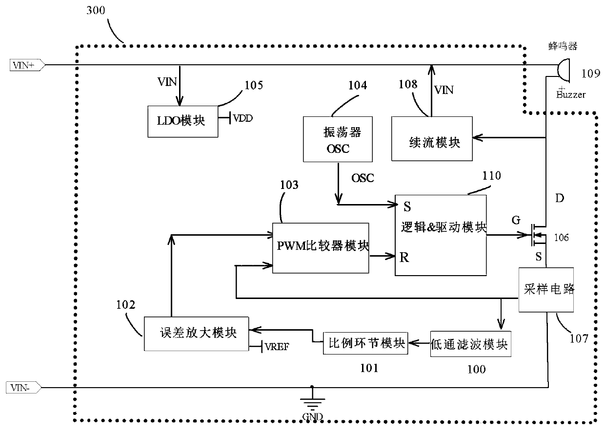
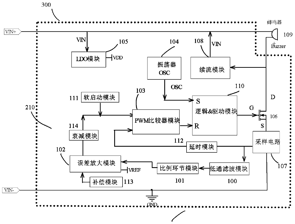
[0050] like figure 2 Shown is a circuit control logic block diagram of an embodiment of the present invention, which includes a low-pass filter module 100, a proportional link module 101, an error amplification module 102, a PWM comparison module 103, an oscillator 104, an LDO module 105, and a loop control electronic switch 10. A sampling circuit 107 , a freewheeling module 108 and a logic and driving module 110 .

[0051] The reference terminal D of the loop control electronic switch 106 is connected to the negative terminal of the buzzer, and the output terminal S is grounded after the sampling circuit 107, so that the loop control electronic switch 106 is connected in series on the buzzer loop, and the two ends of the freewheeling module 108 are respectively It is connected to the positive terminal and the negative terminal of the buzzer, and when the circuit of the buzzer is discon...


PUM


Abstract

The invention discloses an average current type buzzer driving circuit. The average current type buzzer driving circuit comprises a loop control electronic switch, a follow current module, a low passfiltering module, a proportional link module, an error amplification module, a PWM comparator module, an oscillator, a sampling circuit and a logic and drive module; the sampling circuit samples the current on a series loop, and the sampling circuit outputs a sampling signal to a non-inverting input terminal of the PWM comparator module and the low pass filtering module; the low pass filtering module outputs the direct current component to the proportional link module, the proportional link module outputs a voltage signal to the error amplification module, and the error amplification module outputs an error amplification signal to an inverting input terminal of the PWM comparator module; and the output end of the PWM comparator module is connected to the reset end of the logic and drive module, the oscillator outputs a clock signal to the set end of the logic and drive module, the output end of the logic and drive module is connected to the control end of the loop control electronic switch. The sound pressure consistency of the average current type buzzer driving circuit is good.

Description

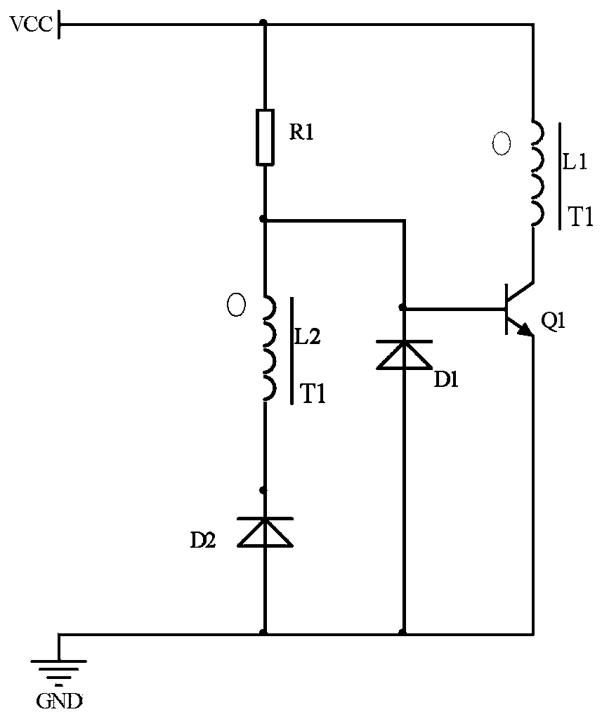
technical field [0001] The invention relates to an average current type buzzer driving circuit. Background technique [0002] The traditional electromagnetic buzzer driving circuit generally uses a triode and a transformer to form a self-excited oscillation circuit, such as figure 1 As shown, first, when the circuit is powered on, the base junction capacitance of the transistor Q1 is charged through the resistor R1. When the base junction capacitance voltage of the transistor Q1 reaches the turn-on threshold of the transistor Q1, the transistor Q1 is turned on, and the voltage source VCC The excitation inductance of the buzzer is charged through the triode Q1, and the upper positive and lower negative induced electromotive force is generated at the same-named end of the inductance L1 and L2. The transistor Q1 is in a saturated conduction state. When the current of the inductor L1 reaches the maximum value, the change of the magnetic flux is zero, the induced electromotive ...

Claims


Application Information

Patent Timeline
Patent Type & Authority Applications(China)
IPC IPC(8): G10K9/13
CPCG10K9/13
Inventor 尹向阳黄天华
Owner SHENZHEN NANYUN MICROELECTRONICS CO LTD
Learn More