Back light source drive circuit and television

A technology for driving circuits and backlight sources, which is applied to TVs, color TVs, and components of color TVs, etc., can solve the problem of many devices, and achieve the effect of simplifying the driving circuit, reducing the number of devices used, and implementing the circuit easily.

Active Publication Date: 2011-10-19
HISENSE VISUAL TECH CO LTD
View PDF5 Cites 14 Cited by
  • Summary
  • Abstract
  • Description
  • Claims
  • Application Information

AI Technical Summary

Problems solved by technology

This part requires a special driver chip to cooperate with the Boost topology peripheral circuit, and there are many devices

Method used


Image

  • Back light source drive circuit and television
  • Back light source drive circuit and television
  • Back light source drive circuit and television

Examples


Embodiment Construction

[0027] The present invention will be further described below in conjunction with the accompanying drawings.

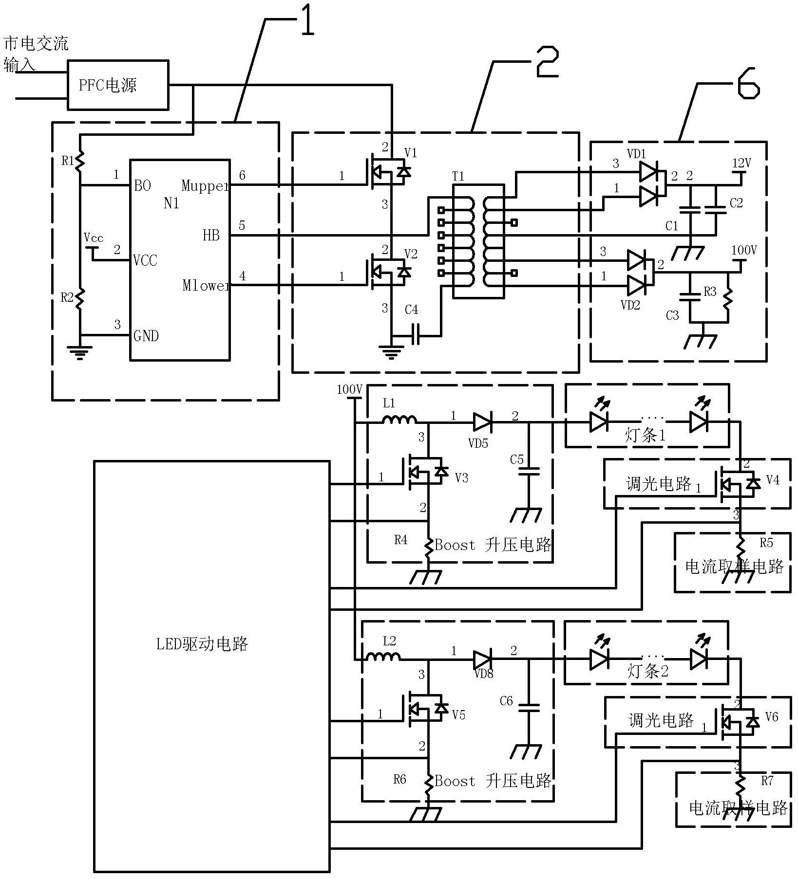
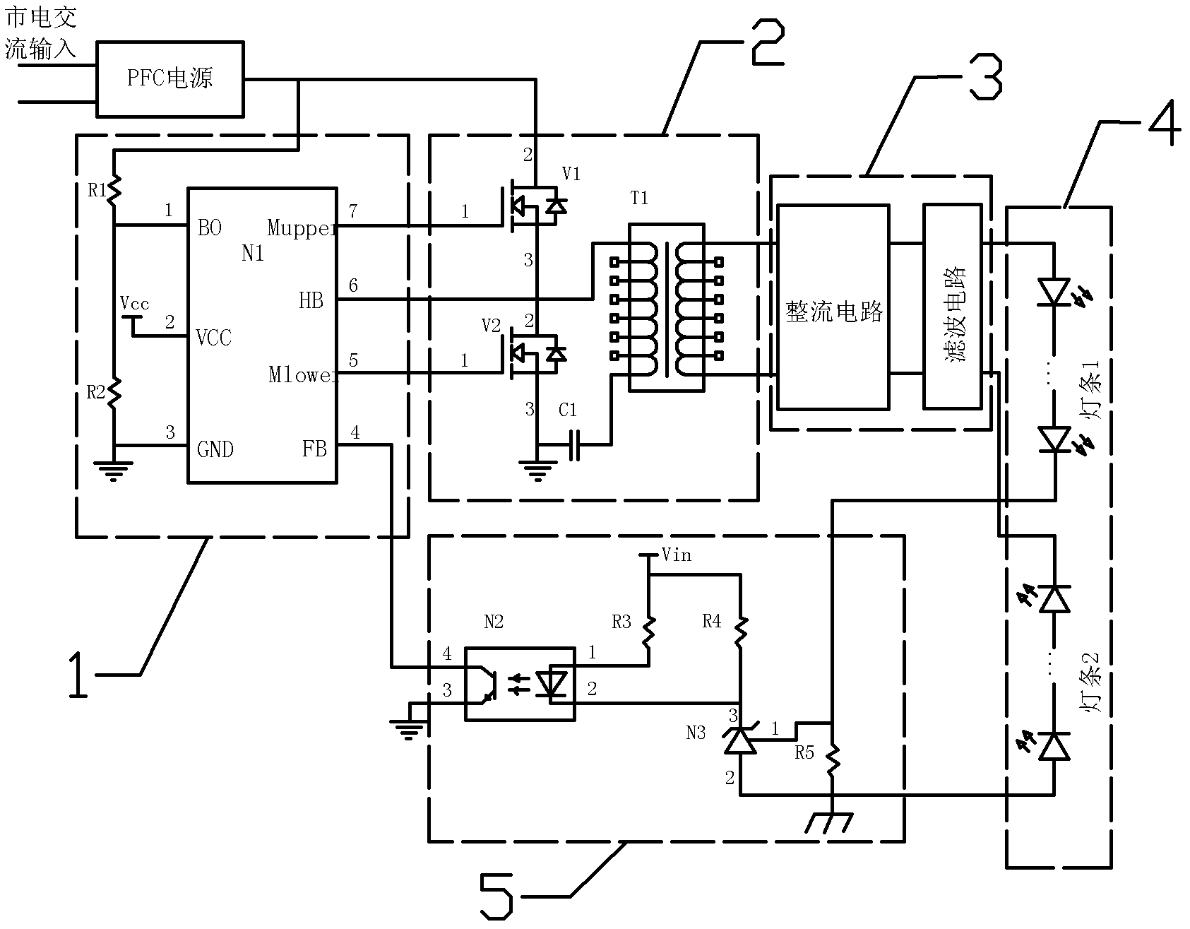
[0028] like figure 2 As shown, a backlight driving circuit according to an embodiment of the present invention includes a primary resonant circuit, a secondary light bar circuit 4, and an optically isolated feedback circuit that functions as an optocoupler feedback, wherein,

[0029] The primary resonant circuit generates a driving pulse signal according to the received external voltage and the current signal fed back by the optical isolation feedback circuit, and provides the required working voltage to the secondary light bar circuit 4 according to the driving pulse signal;

[0030] The optical isolation feedback circuit 5 samples the current of the load in the secondary light bar circuit in real time, and feeds back the current signal to the primary resonant circuit.

[0031] As a further embodiment of the present invention, the primary resonance circuit includes ...


PUM


Abstract

The invention discloses a back light source drive circuit directly driving a lamp strip circuit by using a primary half-bridge resonance circuit. The back light source drive circuit comprises a primary resonance circuit, a secondary lamp strip circuit and an optical isolating feedback circuit having an optical coupling feedback function, wherein the primary resonance circuit generates a driving pulse signal according to the received external voltage and a current signal fed back by the optical isolating feedback circuit, and provides needed work voltage for the secondary lamp strip circuit according to the driving pulse signal; and the optical isolating feedback circuit samples the loaded current in the secondary lamp strip circuit in real time, and feeds back the current signal to the primary resonance circuit. The back light source drive circuit directly lightens and controls the back light source by using the primary half-bridge resonance circuit; and optical coupling is used as the feedback control from the secondary level to the primary level. The drive circuit is simplified so as to eliminate a secondary side LED driving chip, and reduce device number of the whole system.

Description

technical field [0001] The invention relates to the technical field of a liquid crystal display backlight source, in particular to a backlight source drive circuit and a television set. Background technique [0002] LEDs have been widely used in LCD TVs as backlight sources. At present, there are at least two or more light strips in the backlight source of medium and large-sized LED LCD TVs. The driving mode of the power supply is to drive one LED light bar with one booster circuit, and realize the equal current of each light bar by sampling the current of each light bar, so as to meet the requirements of TV screen display. Multi-channel light strips generally use low-voltage 24V input. This method generally requires more chips and peripheral components, and the cost is relatively high. [0003] At present, 42-inch and 46-inch LED LCD TVs have two or more street light bars, and the power supply structure and driving methods used are as follows: figure 1 . [0004] The po...

Claims


Application Information

Patent Timeline
Patent Type & Authority Applications(China)
IPC IPC(8): G09G3/36H04N5/63
Inventor 孟现策迟洪波辛晓光韩文涛
Owner HISENSE VISUAL TECH CO LTD
Why Eureka
Try Eureka