Method and apparatus for increasing the capacity and stability of a single-pole tower

a single-pole tower and capacity technology, applied in the direction of towers, buildings, constructions, etc., can solve the problems of increasing construction costs, concomitant incise, increasing the cost of land or easements, etc., to increase the capacity and stability of a single-pole tower, stabilize the additional load, and stabilize the load

Inactive Publication Date: 2009-09-22
RITZ TELECOMM
View PDF40 Cites 21 Cited by
  • Summary
  • Abstract
  • Description
  • Claims
  • Application Information

AI Technical Summary

Benefits of technology

[0010]The present invention provides a method and an apparatus for increasing the capacity and stability of a single-pole tower. The invention thus provides a support structure for use with an existing single pole tower. The single pole tower has a pole anchored to a foundation and supports a first load. The support structure has a number of sleeves surrounding the pole. The sleeves may extend beyond the height of the existing single pole tower. A first one of the sleeves is anchored to the foundation. A second load is attached to a second one of the sleeves.
[0014]A further embodiment of the present invention provides a support structure for supporting a load and for use with an existing single pole tower. The single pole tower may include a pole anchored to a foundation. The support structure may include a number of sleeves surrounding the pole. One of the sleeves may be anchored to the foundation and another one of the sleeves may support the load. A number of load transfer pins may be positioned along the sleeves. The pins extend from the sleeves to the pole so as to stabilize the load.
[0016]A method of the present invention provides for placing an additional load on a single pole tower. The single pole tower includes a pole anchored to a foundation. The method includes the steps of positioning one or more sleeves around the pole, anchoring the sleeves to the foundation, and supporting the additional load on the sleeves. A first one of the number of sleeves may be anchored to the foundation, a second one of the sleeves may be supporting the additional load, and one or more joinder sleeves may attach the first and the second sleeves. The method may further include the step of attaching a number of load transfer pins to the sleeves so as to stabilize the additional load.
[0017]Thus, it is an object of the present invention to provide an improved method and apparatus for increasing the capacity and stability of a single-pole tower.
[0018]It is another object of the present invention to provide an improved method and apparatus for increasing the capacity and stability of a single-pole tower wherein the apparatus will support the weight of additional equipment and the additional environmental forces exerted on the pole.
[0019]It is still another object of the present invention to provide an improved method and apparatus for increasing the capacity and stability of a single-pole tower wherein the apparatus will support the weight of additional equipment and the additional environmental forces exerted on the pole while also providing sufficient stability to resist the forces known as bending moments caused by the new equipment and the environmental forces.

Problems solved by technology

The increase in wireless telecommunications traffic has resulted a concomitant incise in the need for pole-mounted transmission equipment of all kinds.
Purchasing land or easements, however, is becoming increasingly expensive, particularly in urban areas where the need for wireless telecommunications is greatest.
Zoning regulations often limit the construction of new towers in the vicinity of existing towers or may prohibit the construction of new towers in the most suitable locations.
The expense and delay associated with the zoning process often may be cost-prohibitive or so time-consuming that construction of the new tower is not feasible.
The equipment and the environmental factors produce forces known as bending moments that, in effect, may cause a single-pole tower to overturn if not designed for adequate stability.
Further, these ground-based systems only function when the damaged pole section is sufficiently near the ground for the bracket assembly to be attached to the ground spikes.

Method used


Image

  • Method and apparatus for increasing the capacity and stability of a single-pole tower
  • Method and apparatus for increasing the capacity and stability of a single-pole tower
  • Method and apparatus for increasing the capacity and stability of a single-pole tower

Examples


Embodiment Construction

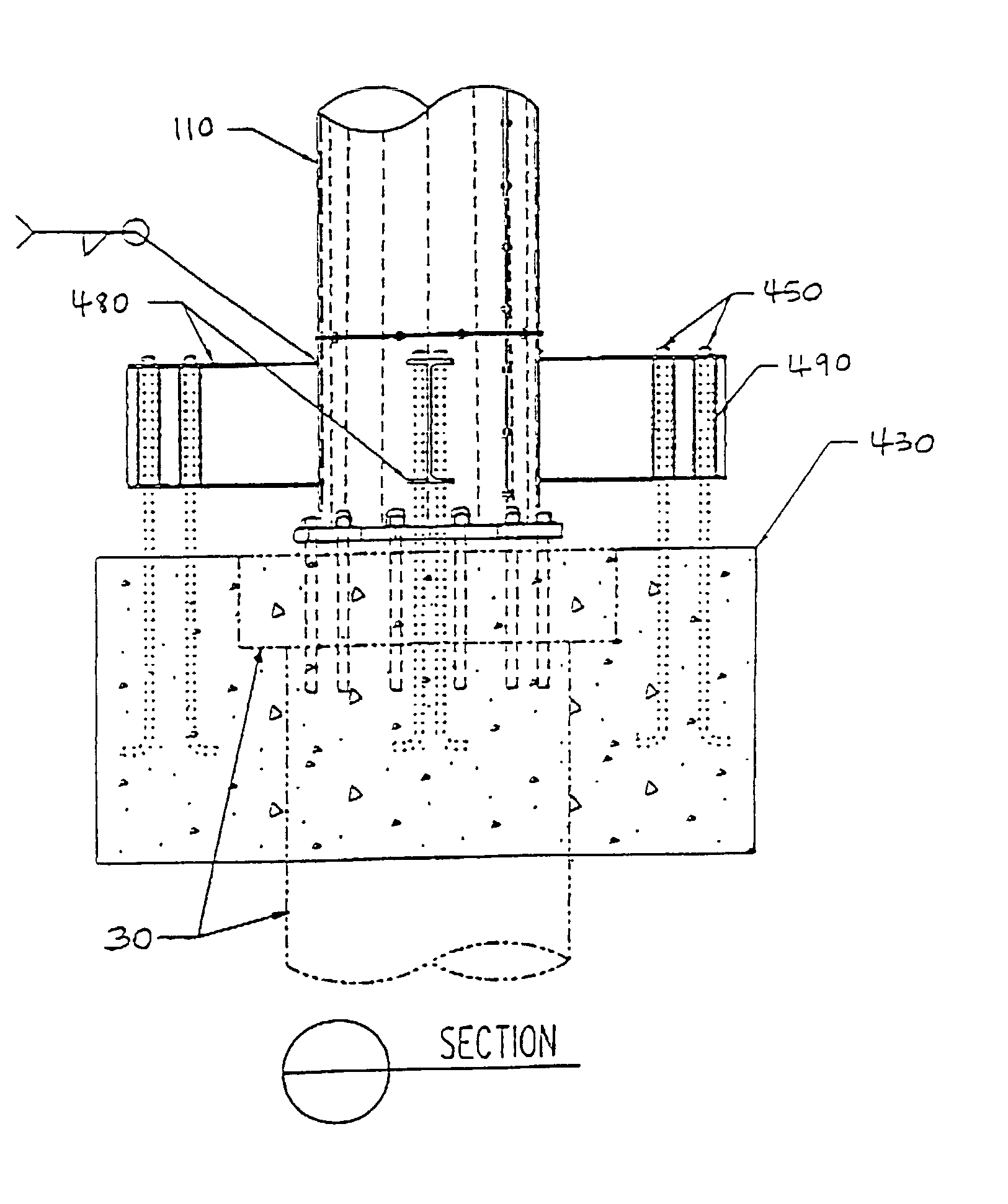
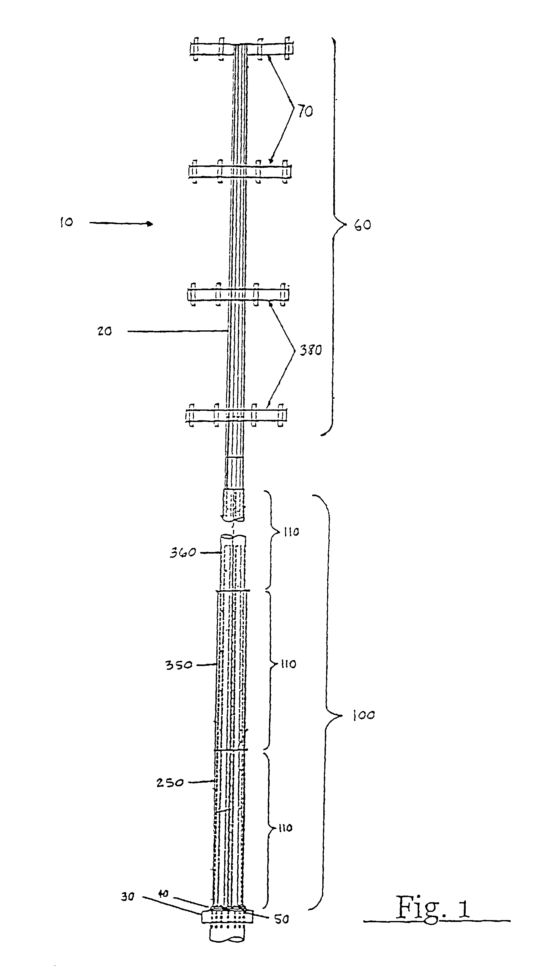
[0029]Referring now in more detail to the drawings, in which like numerals indicate like elements throughout the several views, FIG. 1 shows a single pole tower 10 for use with the present invention. As is well known in the art, the single pole tower 10 generally includes a pole 20 of varying height. The pole 20 is generally a hollow structure made from various types of steel, composite materials, or other types of sufficiently rigid materials. The pole 20 may be a tapered structure such that it decreases in width as its height increases. The pole 20 may be mounted on a foundation 30 by a base plate 40 and a plurality of anchor bolts 50. The foundation 30 is generally a reinforced concrete structure that may by anchored by conventional means. The base plate 40 and the anchor bolts 50 are generally made from various types of steel or other types of sufficiently rigid materials. One or more loads 60 may be fixedly attached to the pole 20. In the present embodiment, the load 60 may inc...


PUM


Abstract

A support structure for use with an existing single pole tower. The single pole tower has a pole anchored to a foundation and supports a first load. The support structure has a number of sleeves surrounding the pole. A first one of the sleeves is anchored to the foundation. A second load is attached to a second one of the sleeves.

Description

[0001]This application is a continuation of and claims priority benefits to U.S. patent application Ser. No. 09 / 706,216, entitled “Method and Apparatus for Increasing the Capacity and Stability of a Single-Pole Tower,” and filed on Nov. 3, 2000 now U.S. Pat. No. 6,453,636. U.S. patent application Ser. No. 09 / 706,216 is a continuation of an claims priority benefits to U.S. patent application Ser. No. 09 / 557,266, entitled “Method and Apparatus for Increasing the Capacity and Stability of a Single-Pole Tower,” and filed on Apr. 24, 2000 now abandoned.TECHNICAL FIELD[0002]The present invention relates generally to a method and an apparatus for increasing the capacity and stability of a single-pole tower. More particularly, the invention relates to a method and an apparatus that employs a sleeve and an array of load transfer pins to add structural stability to a single-pole tower and thereby increase its capacity to support additional equipment and withstand environmental loads.BACKGROUN...

Claims


Application Information

Patent Timeline
Patent Type & Authority Patents(United States)
IPC IPC(8): E04B1/00E04H12/22
CPCE04H12/2292
Inventor RITZ, CHARLES D.
Owner RITZ TELECOMM
Why Eureka
Try Eureka