Lighting system

A lighting system and pulse width modulation technology, applied in the field of lighting systems, can solve problems such as light source stroboscopic, and achieve the effect of avoiding damage, ensuring dimming accuracy, and avoiding light source stroboscopic

Inactive Publication Date: 2019-10-15
MIDEA INTELLIGENT LIGHTING & CONTROLS TECH CO LTD
View PDF4 Cites 2 Cited by
  • Summary
  • Abstract
  • Description
  • Claims
  • Application Information

AI Technical Summary

Problems solved by technology

[0002] At present, after the lighting equipment using LED (Light Emitting Diode, light-emitting diode) light source

Method used


Image

  • Lighting system
  • Lighting system
  • Lighting system

Examples


Embodiment 1

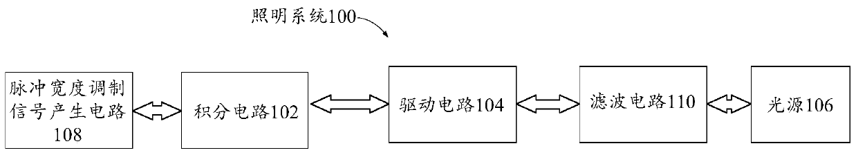
[0040] Such as figure 1 and figure 2 As shown, according to one aspect of the present invention, a lighting system 100 is provided, comprising: an integrating circuit 102 , a driving circuit 104 and a light source 106 .

[0041] Specifically, the input terminal of the integration circuit 102 is connected to the pulse width modulation signal, and the integration circuit is used to convert the pulse width modulation signal into an analog signal; the output terminal of the integration circuit 102 is connected to the control terminal of the drive circuit 104; the output of the drive circuit 104 The terminal is connected to the light source 106, and the light source 106 works under the drive of the driving circuit 104; wherein, the duty cycle corresponding to the pulse width modulation signal is proportional to the voltage corresponding to the analog signal.

[0042] In this embodiment, the lighting system includes an integrating circuit 102, a driving circuit 104 and a light sourc...

Embodiment 2

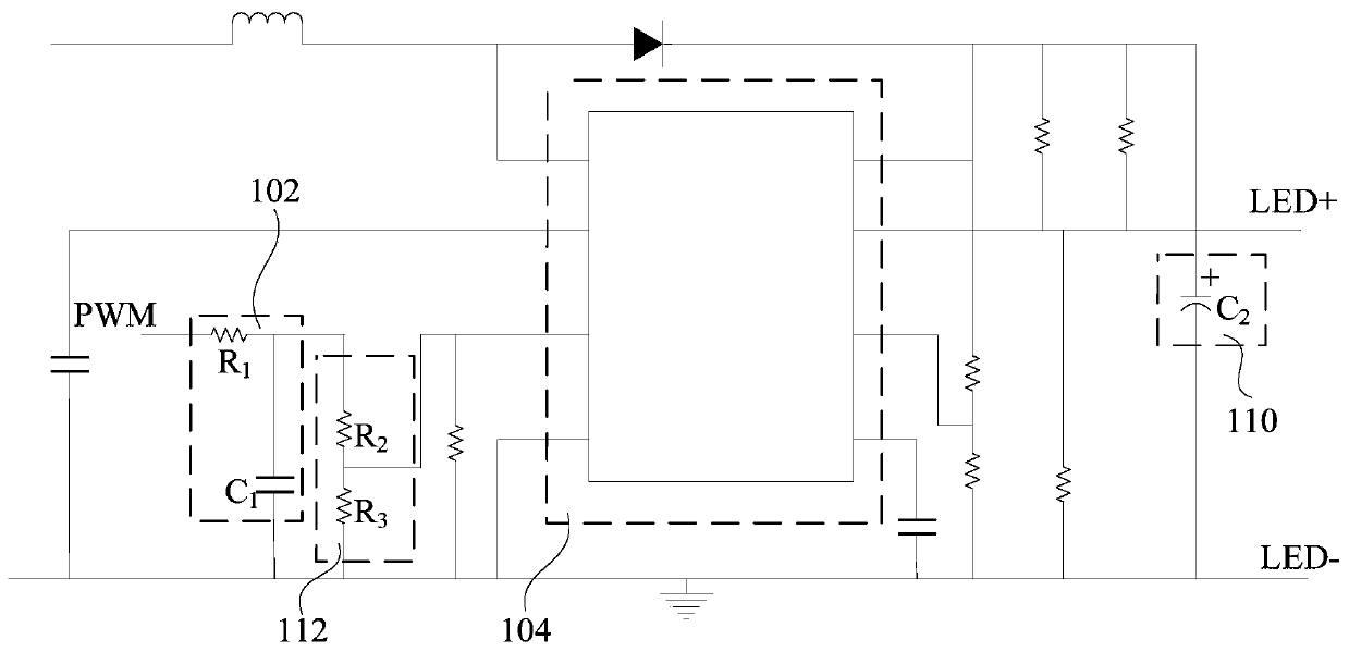
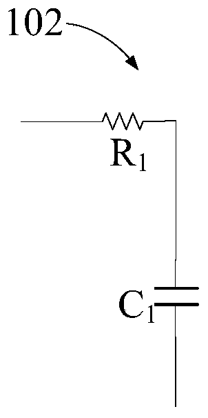
[0047] In one embodiment of the present invention, the lighting system 100 includes: an integrating circuit 102 , a driving circuit 104 and a light source 106 . Among them, such as image 3 As shown, the integrating circuit 102 includes a first resistor R 1 and with the first resistor R 1 Connect the first capacitor C 1 .

[0048] In this embodiment, the integrator circuit 102 is realized by using low-cost resistors and capacitors. Specifically, the first resistor R 1 Connected between the drive circuit 104 and the input end of the pulse width modulation signal, the first resistor R 1 One end receives the pulse width modulation signal, and the other end is connected to the first capacitor C 1 It is connected to the drive circuit 104. The first capacitance C 1 One end is connected to the first resistor R 1 and drive circuit 104, the first capacitor C 1 The other end of the ground.

[0049] The pulse width modulation signal (i.e. PWM signal) includes three parameters ...

Embodiment 3

[0058] Such as figure 1 and figure 2 As shown, in an embodiment of the present invention, the lighting system 100 includes: a pulse width modulation signal generating circuit 108 , an integrating circuit 102 , a driving circuit 104 and a light source 106 . Wherein, the pulse width modulation signal generation circuit 108 is connected to the input end of the integration circuit 102, and the pulse width modulation signal generation circuit 108 is used for generating a pulse width modulation signal.

[0059] In this embodiment, the lighting system is provided with a pulse width modulation signal generating circuit 108 for generating a corresponding pulse width modulation signal according to a dimming command issued by a host computer, a controller and other equipment. Specifically, the output end of the pulse width modulation signal generation circuit 108 is connected to the input end of the integration circuit 102, and the generated pulse width modulation signal is transmitted...


PUM


Abstract

The invention provides a lighting system, which comprises an integrating circuit, a driving circuit and a light source. A pulse width modulation signal is connected into the input end of the integrating circuit, and the integrating circuit is used to convert the pulse width modulation signal into an analog signal. The control end of the driving circuit is connected into the output end of the integrating circuit. The output end of the driving circuit is connected with the light source. The duty cycle corresponding to the pulse width modulation signal is directly proportional to the voltage corresponding to the analog signal. The lighting system of the invention avoids the stroboflash problem of the light source caused by direct PWM dimming. At the same time, because the voltage value of theanalog signal output by the integrating circuit is directly proportional to the duty cycle of the input pulse width modulation signal, the process of adjusting the brightness of the light source through the analog signal is synchronized with the PWM dimming signal. Therefore, flicker-free dimming is realized on the premise of ensuring the dimming accuracy, and the damage to the human body causedby the stroboflash of the light source is avoided.

Description

technical field [0001] The present invention relates to the technical field of lighting control, in particular to a lighting system. Background technique [0002] At present, after functions such as dimming and communication are added to lighting equipment using LED (Light Emitting Diode, light emitting diode) light source, the problem of "stroboscopic" of the light source is serious. The so-called strobe refers to the continuous fluctuation or flickering of light during the switching cycle. Relevant studies have shown that strobe at a specific frequency can cause headaches, eye fatigue, photosensitive epilepsy, vision loss, distraction and other hazards. [0003] Therefore, there is an urgent need for a lighting system to solve the flickering problem of the light source with dimming function. Contents of the invention [0004] The present invention aims to solve at least one of the technical problems existing in the prior art or related art. [0005] To this end, the o...

Claims


Application Information

Patent Timeline
IPC IPC(8): H05B33/08H05B44/00
CPCH05B45/10Y02B20/30
Inventor 杜鹏杰梁琚胤李小勇
Owner MIDEA INTELLIGENT LIGHTING & CONTROLS TECH CO LTD
Why Eureka
Try Eureka