Prosthetic knee implant systems and methods with linked tibial rotation

A tibial, bearing surface technology for orthopedic devices that addresses issues such as poor rotation of the tibial component

Active Publication Date: 2019-10-15
ZIMMER INC
View PDF18 Cites 2 Cited by
  • Summary
  • Abstract
  • Description
  • Claims
  • Application Information

AI Technical Summary

Problems solved by technology

In some cases, this can lead to poor rotation of the tibial component relative to the femoral component

Method used


Image

  • Prosthetic knee implant systems and methods with linked tibial rotation
  • Prosthetic knee implant systems and methods with linked tibial rotation
  • Prosthetic knee implant systems and methods with linked tibial rotation

Examples


Embodiment Construction

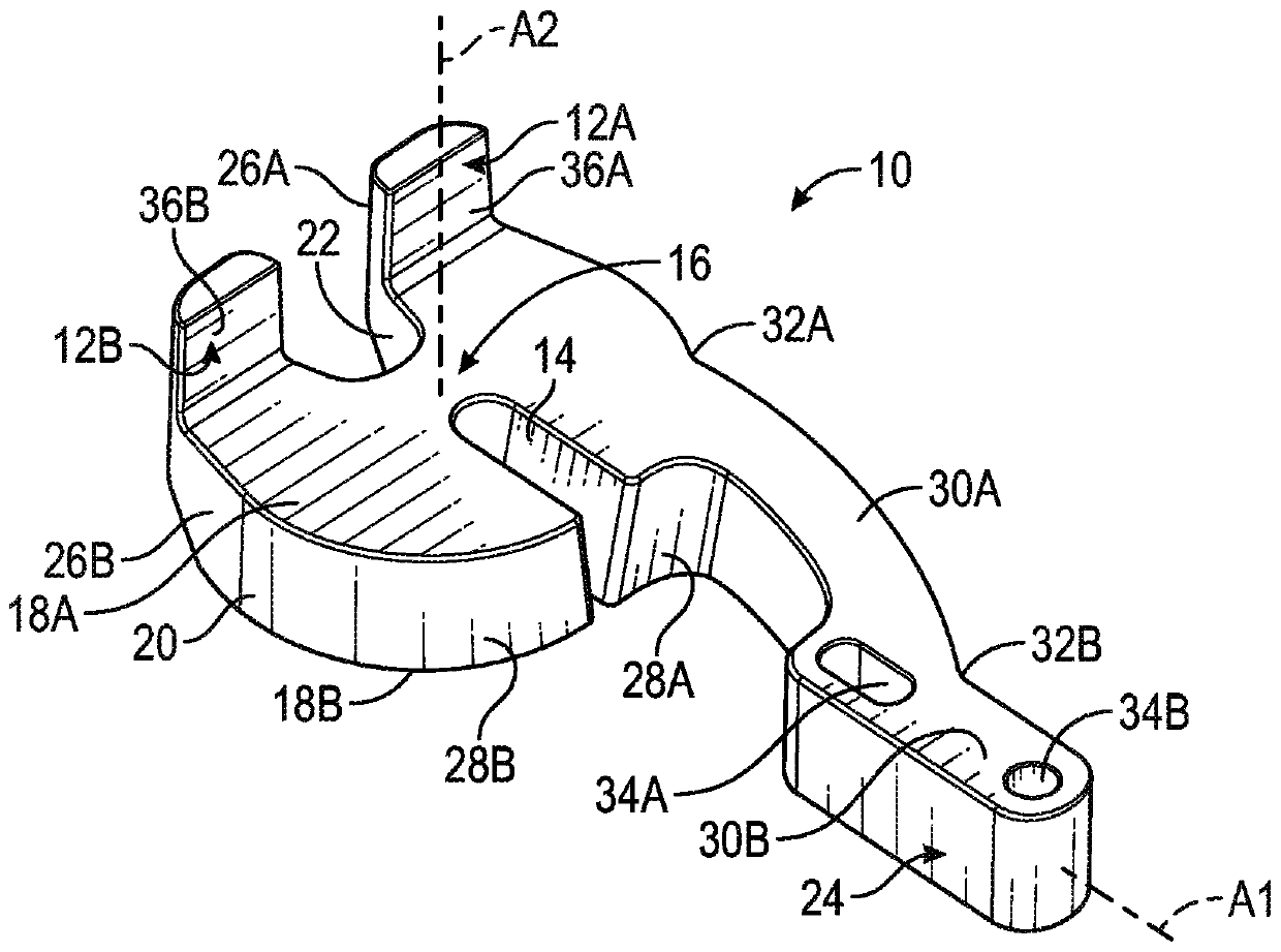
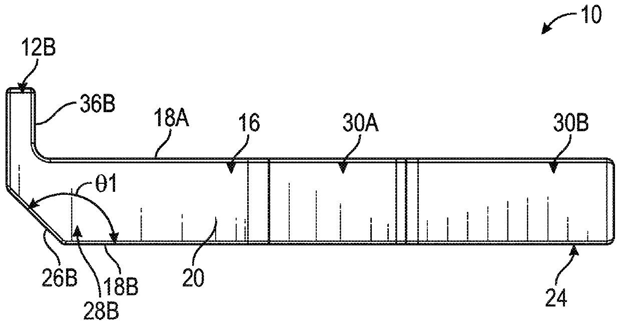
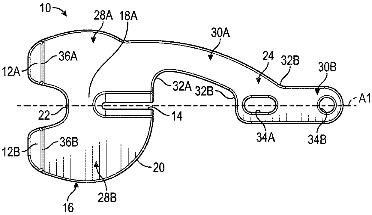
[0045] figure 1 is a perspective view of tibial spacer plate 10 with alignment feet 12A and 12B and index slot 14 disposed in spacer block 16 . figure 2 yes figure 1 A side view of tibial spacer 10, showing the angle of alignment feet 12A and 12B relative to bearing surface 18A. image 3 yes figure 1 A top view of the tibial spacer of , showing the position of the indicator groove 14. Discuss at the same time Figure 1 to Figure 3 .

[0046] The spacer block 16 may include a first bearing surface 18A, a second bearing surface 18B, an edge perimeter surface 20 , a notch 22 and a handle 24 . Edge perimeter surface 20 may include chamfers 26A and 26B opposite alignment feet 12A and 12B, respectively. The notch 22 and the index groove 14 may extend into the spacer block 16 to form a first condyle portion 28A and a second condyle portion 28B. The handle 24 may extend from the edge peripheral surface 20 of the spacer block 16 and may include a first segment 30A and a second ...


PUM


Abstract

A tibial spacer paddle (10) comprises a spacer block (16) comprising opposing bearing surfaces (18A, 18B), an alignment slot (14) extending into the spacer block; and a handle extending from the spacer block. The spacer block can include feet (12A, 12B) for passively engaging the femur or pegs (112A, 112B) for actively engaging a femoral component so that the spacer block is linked to the femur while the tibia rotates. A tibial spacer system comprises a provisional component having an alignment tab (222) extending from a body and an alignment indicator located on the body, a femoral component(240) and a pin (264) extending from the femoral component. The pin can engage the alignment tab so that the provisional component is linked to the femur while the tibia rotates. In addition to or alternatively to the alignment tab and pin, the provisional component can include a tibial plate (30) that can be rotationally connected to the provisional component.

Description

[0001] priority statement [0002] This application claims the benefit of U.S. Provisional Patent Application No. 62 / 464076, filed February 27, 2017, from which priority benefit is claimed herein, and is incorporated herein by reference in its entirety. technical field [0003] This document generally relates to, but is not limited to, orthopedic implant systems and methods for knee arthroplasty. More specifically, the present disclosure relates to, but is not limited to, orthopedic devices and methods for matching medial / external rotation of a tibial component to medial / external rotation of a femoral component. Background technique [0004] The natural knee usually undergoes some degree of rotation between the tibia and femur during flexion. Specifically, the femur can rotate in a transverse plane relative to the tibia. Accordingly, it may be desirable to replicate the natural rotational alignment of the tibia and femur when implanting one or more orthopedic femoral and t...

Claims


Application Information

Patent Timeline
Patent Type & Authority Applications(China)
IPC IPC(8): A61F2/46
CPCA61F2/4684A61F2/3868A61F2/3859A61F2/4657A61F2/384A61F2/30771A61F2002/4658A61F2/389A61F2/3886
Inventor B·D·厄尔A·P·沃尔夫
Owner ZIMMER INC
Why Eureka
Try Eureka