Forklift operating rod bending device
A joystick and bending rod technology, applied in the field of forklift joystick bending rod devices, can solve the problems of excessive bending angle, affecting the installation and subsequent use of the joystick, and achieve the effect of avoiding excessive bending
- Summary
- Abstract
- Description
- Claims
- Application Information
AI Technical Summary
Problems solved by technology
Method used
Image

Examples
Embodiment 1
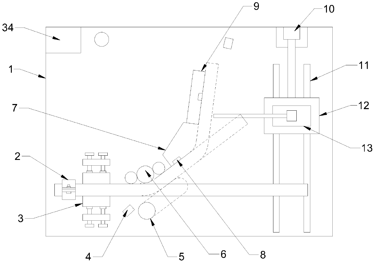
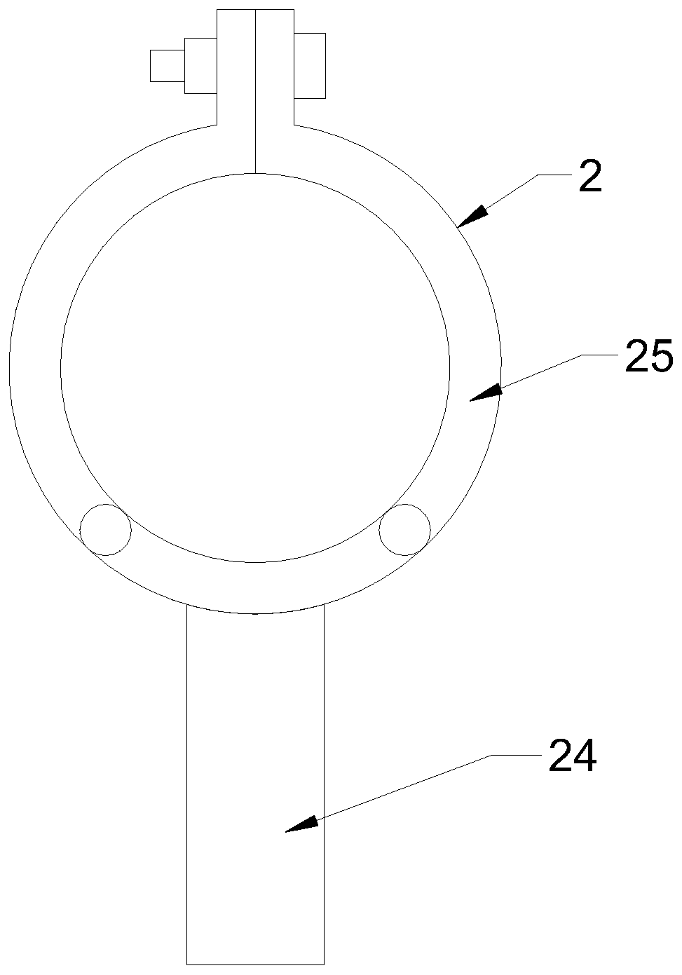
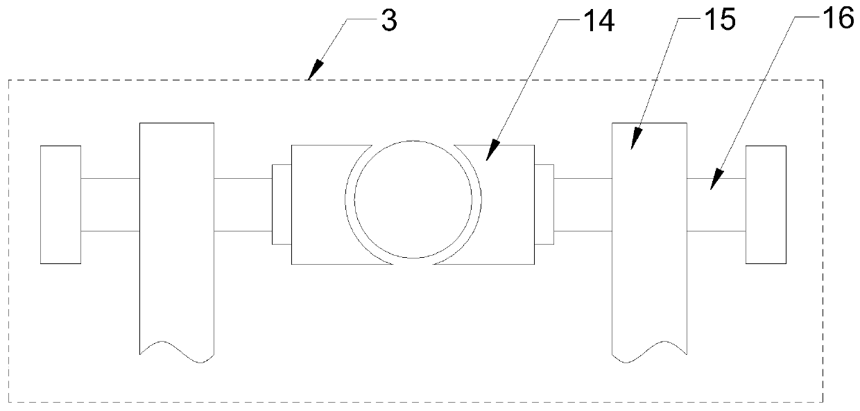
[0026] see Figure 1~6 , in an embodiment of the present invention, a forklift joystick bending device, including a base 1, a fixing mechanism 3 arranged above the base 1, a positioning roller 6, a positioning block 7, a positioning plate 9, an alarm and a PLC programming controller 34. The upper end surface of the base 1 is provided with a hoop 2 near the position of the fixing mechanism 3, the positioning roller 6 is arranged on the side of the fixing mechanism 3 away from the hoop 2, and the side of the fixing mechanism 3 is provided with a No. 1 bending mechanism 5, a One side of the number bending mechanism 5 is equipped with an infrared angle measuring instrument 4, the positioning block 7 and the positioning plate 9 are arranged on the side of the positioning roller 6 away from the fixing mechanism 3, and the side of the positioning plate 9 is also equipped with an infrared angle measuring instrument 4 , and the distance sensor 8 is installed on the positioning block 7 ...
Embodiment 2
[0029] see figure 1 and Figure 5-6 The No. 1 bending mechanism 5 is obliquely arranged on the base 1. The No. 1 bending mechanism 5 includes a bottom plate 22, a symmetrical No. 1 rack 19 arranged on both sides of the bottom plate 22, and meshing with the No. 1 rack 19 on both sides respectively. The No. 1 gear 18 and the column 23 arranged on the top of the base plate 22, the column 23 is installed in the middle of the upper end surface of the base plate 22 through bearings, the No. 1 gear 18 is fixed on the end of the output shaft of the positive and negative motor 17, and the bottom of the base plate 22 Several No. 2 slide blocks 21 are installed at the end, and No. 2 slide rails 20 are installed on the base 1 corresponding to the No. 2 slide blocks 21, and the base plate 22 moves along the No. 2 slide rails 20 by the No. 2 slide blocks 21.
[0030] In this embodiment, by setting the No. 1 bending mechanism 5 and setting the No. 1 bending mechanism 5 obliquely, the cylind...
Embodiment 3
[0032] see figure 1 and Figure 5, No. 2 bending mechanism 13 comprises support table 12, support column 27, No. 2 rack 28, No. 2 gear 30 and No. 2 cylinder 32, and support column 27 is installed on the upper end face of support platform 12 by bearing, and No. 2 gear 30 Fixed on the end of the output shaft of the motor 29, the second rack 28 is fixed on the outer wall of the support column 27, the second rack 28 is connected to the second gear 30 by a chain 31, and the second cylinder 32 is fixed on the top of the support column 27, The end of the piston rod of the No. 2 cylinder 32 is fixed with an arc-shaped push plate 33, and an anti-skid pad is pasted on the inner wall of the push plate 33; There is a No. 1 slide rail 11 corresponding to the No. 1 slide block 26, and the support table 12 moves along the No. 1 slide rail 11 through the No. 1 slide block 26. A side of the No. 1 slide rail 11 away from the No. 1 bending mechanism 5 is installed. No. cylinder 10, the end of ...
PUM
 Abstract
Description
Claims
Application Information
 - R&D Engineer
- R&D Manager
- IP Professional
- Industry Leading Data Capabilities
- Powerful AI technology
- Patent DNA Extraction
Browse by: Latest US Patents, China's latest patents, Technical Efficacy Thesaurus, Application Domain, Technology Topic.
© 2024 PatSnap. All rights reserved.Legal|Privacy policy|Modern Slavery Act Transparency Statement|Sitemap