
Anti-theft lock core and unlocking method

An anti-theft lock cylinder and unlocking technology, which is used in building locks, non-mechanical transmission-operated locks, time registers, etc., can solve problems such as failure to unlock normally, large driving motor current, vibration, weak strong magnetic protection, etc., to avoid Poor anti-theft ability, stable unlocking cam, avoid excessive bending effect

Active Publication Date: 2014-05-07
成都泰然科技有限公司
View PDF7 Cites 3 Cited by
  • Summary
  • Abstract
  • Description
  • Claims
  • Application Information

AI Technical Summary

Problems solved by technology

Most of the traditional electronic locks are large in size, and the current required to drive the motor is large when unlocking, and the power consumption is also large, which makes the current electronic locks unsuitable for padlocks or small locks.
Although there are smart lock cylinders controlled by miniature electromagnets on the market, such lock cylinders are relatively weak against vibration and strong magnetism, resulting in relatively weak anti-technical opening capabilities.
At the same time, due to my country's industry standard for electronic locks, all electronic locks must be equipped with mechanical unlocking methods to prevent normal unlocking when the electronic unlocking fails.
At present, all electronic locks with mechanical unlocking are independent of electronic unlocking and mechanical unlocking. The anti-theft method of unlocking is useless
Some foreign electronic locks do not have a mechanical unlocking structure. If the electronic unlocking fails, it can only be unlocked by destroying and replacing the entire lock cylinder.

Method used


Image

  • Anti-theft lock core and unlocking method
  • Anti-theft lock core and unlocking method
  • Anti-theft lock core and unlocking method

Examples


Embodiment Construction

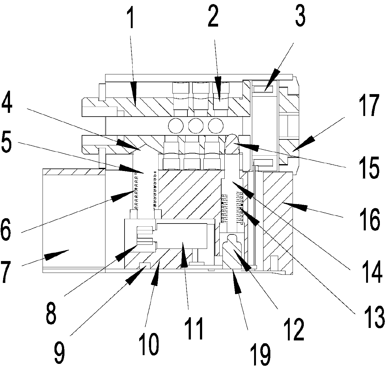
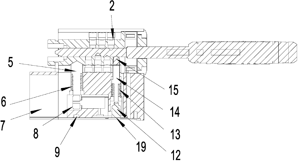
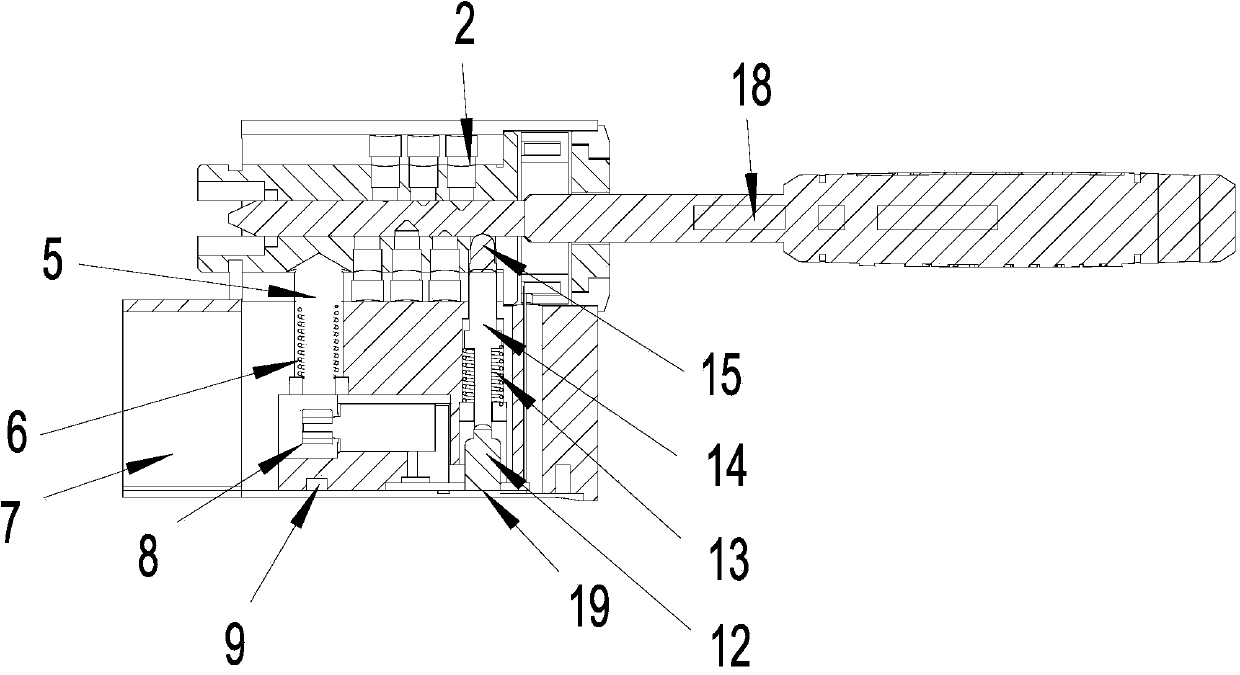
[0025] Such as figure 1 As shown in the anti-theft lock cylinder of the present invention, an unlocking motor 11 and an electrical compartment 7 are provided in the lock cylinder housing 16, and a lock cylinder 1, a mechanical pin 2 and an induction coil 3 are also provided, and a lockhole is also provided at the entrance of the lockhole Cover 17, in order to protect keyhole. A trigger pin 15 is provided near the entrance of the lock hole in the lock core shell 16 , and a part of the trigger pin 15 is located in the lock hole in the lock cylinder 1 . When an object is inserted into the lockhole, the inserted object will press the trigger pin 15, and the trigger pin 15 will make the trigger lever 14 provided with the trigger lever spring 13 contact with the contact 12 connected to the circuit board 19 according to the pressure of the inserted object. After the object exits the keyhole, the trigger pin 15 loses pressure, and the trigger lever 14 resets under the action of the t...


PUM


Abstract

The invention relates to an anti-theft lock core and an unlocking method. According to the invention, an unlocking motor, a lock container and an induction coil are arranged in a lock core casing; a trigger cylinder is arranged near to the inlet of a lock hole and is positioned in the lock hole in the lock container; a trigger rod with a trigger rod spring is in contact with or separated from a contact point through the trigger cylinder under the action of outside pressure, and the contact point is connected with a circuit board; the unlocking motor is arranged on a motor bracket and is connected with the circuit board; the unlocking motor is provided with a rotary unlocking cam; a blind hole with a small upper part and a large lower part is formed the lower side surface of the lock container, and the peripheral wall of the blind hole is an oblique surface; an unlocking cylinder is arranged in the lock core casing, can be inserted into the blind hole, and is pushed out of the blind hole by the peripheral wall of the blind hole when the lock container is rotated; the unlocking cylinder is provided with an unlocking cylinder spring for resetting, and the unlocking cam can support or is separated from the bottom surface of the unlocking cylinder after rotating. The anti-theft lock core has the advantages that the unlocking authentication of mechanical mode and electronic mode can be simultaneously carried out, so that the legality of unlocking and the safety of lock core are greatly improved; when the electronic authentication fails, the pure-mechanical unlocking is realized.

Description

technical field [0001] The invention relates to an anti-theft lock core and an unlocking method, in particular to a lock core with an electronic code and a mechanical anti-theft structure and an unlocking method based on the lock core. Background technique [0002] Electronic lock is a lock form commonly used in some specific fields at present. It controls unlocking or locking by judging the authority of the key inserted into the lock cylinder through the power supply and circuit in the lock body or key body. Most of the traditional electronic locks are large in size, and the current required to drive the motor is large when unlocking, and the power consumption is also large, which makes the current electronic locks unsuitable for padlocks or small locks. Although currently on the market there are smart lock cylinders controlled by miniature electromagnets, such lock cylinders are relatively weak to vibration and strong magnetic protection, resulting in relatively weak anti-...

Claims


Application Information

Patent Timeline
IPC IPC(8): E05B47/00G07C9/00
Inventor 吕茅利王永革卢新亮李红宇
Owner 成都泰然科技有限公司
Learn More