Binding machine

The technology of a binding machine and binding components, which is applied in the field of binding machines, can solve the problems that the discharge distance of the feeding rack is not reached, it is inconvenient to bind books of different thicknesses, and the positions of books and coils are inconsistent, etc., so as to achieve the effect of easy promotion and use, and binding effect Good, simple structure effect

Active Publication Date: 2019-10-18
东莞市优品胜钉装科技有限公司
View PDF13 Cites 2 Cited by
  • Summary
  • Abstract
  • Description
  • Claims
  • Application Information

AI Technical Summary

Problems solved by technology

[0004] The purpose of the present invention is to provide a binding machine to solve the problem that during the use of the existing binding machine mentioned in the above-mentioned background technology, the discharge distance of the feeding rack does not reach the actual size of the product, so that the coil ratio of the discharging The actual use should be short, which will affect the binding effect, and when the binding machine is working, most of the books to be bound are pushed under the binding mechanism. Pushing the product over will easily cause the position of the book and the coil to be inconsistent, resulting in easy deformation when pressing, and the binding platform It cannot be adjusted, and it is inconvenient to bind books of different thicknesses

Method used


Image

  • Binding machine
  • Binding machine
  • Binding machine

Examples


Embodiment Construction

[0022] The following will clearly and completely describe the technical solutions in the embodiments of the present invention with reference to the drawings in the embodiments of the present invention.

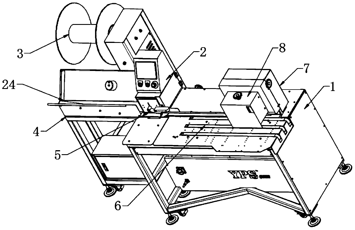
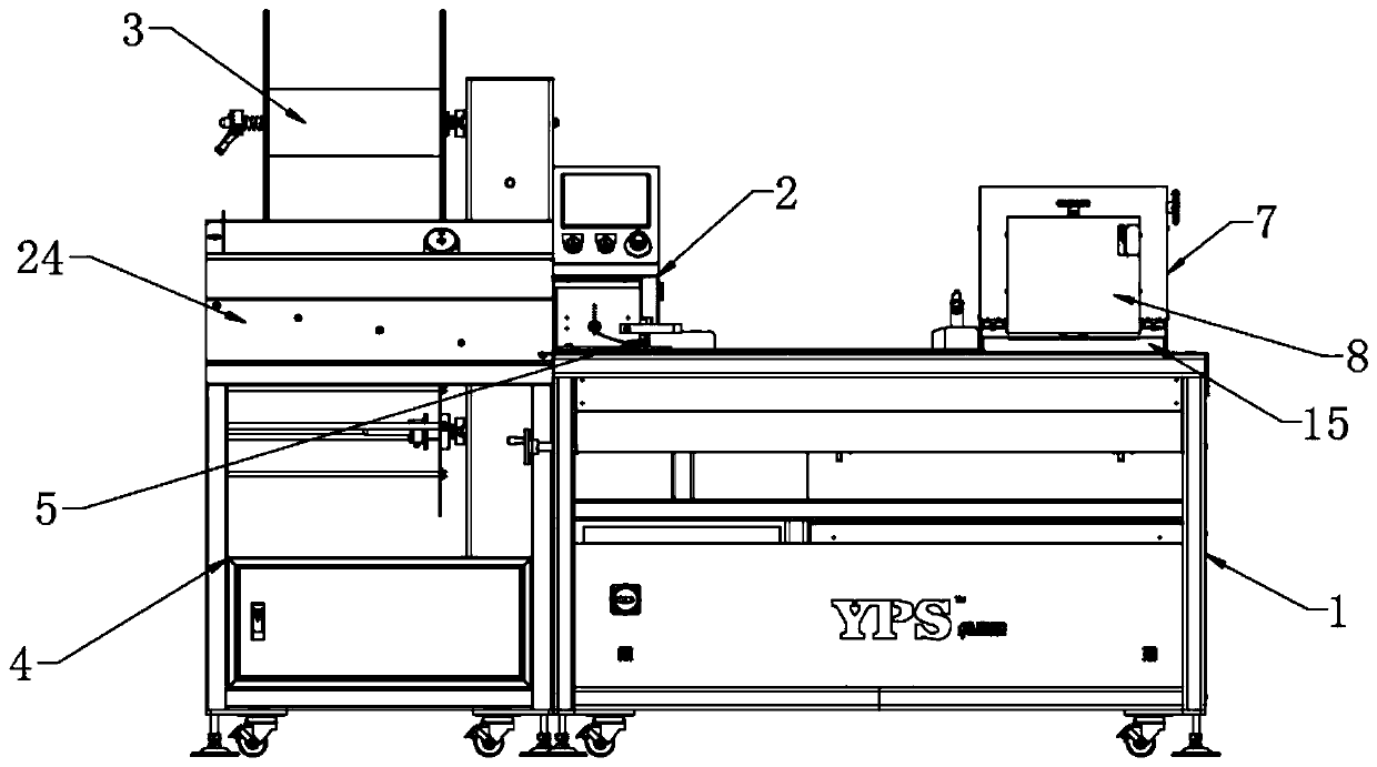
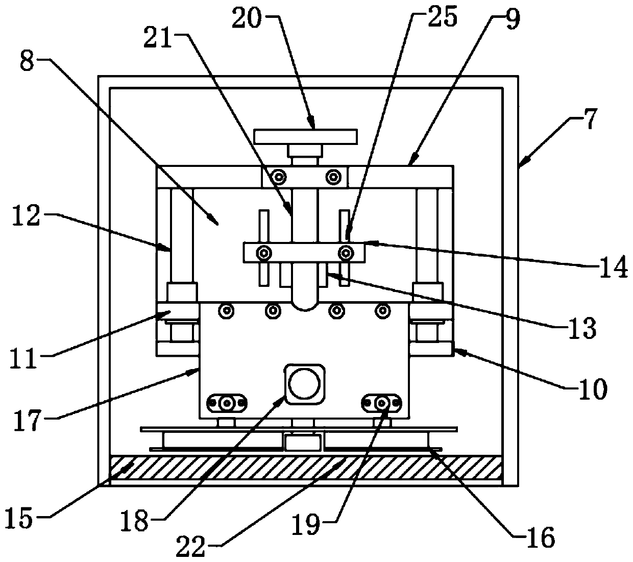
[0023] Such as Figure 1-5 As shown, the present invention provides a technical solution: a binding machine, including a workbench 1 and a feed frame 4, the feed frame 4 is located on the side of the workbench 1, and the surface of the workbench 1 is provided with a control assembly 2, so The surface of the workbench 1 is provided with a transfer platform 6, and one side of the transfer platform 6 is provided with a binding assembly 7, and a positioning assembly 8 is installed on a side wall of the binding assembly 7, and the positioning assembly 8 is located above the transfer platform 6, The positioning assembly 8 is fixedly connected with a No. 1 fixed frame 9 and a No. 2 fixed frame 10, and a pillar 12 is connected between the No. 1 fixed frame 9 and the No. 2 fixed frame ...


PUM


Abstract

The invention discloses a binding machine. The binding machine comprises a working table and a feeding frame, wherein the feeding frame is located on one side of the working table, a control assemblyis arranged on the surface of the working table, a conveying platform is arranged on the surface of the working table, a binding assembly is arranged on one side of the conveying platform, a positioning assembly is arranged on one side wall of the binding assembly, the positioning assembly is located above the conveying platform, a first fixing frame and a second fixing frame are fixedly connectedto the positioning assembly, supporting columns are connected between the first fixing frame and the second fixing frame, and movable frames are connected to the supporting columns in a lifting mode.According to the binding machine, the binding assembly is arranged, the positioning assembly is arranged on one side of the binding assembly, a to-be-bound workpiece can be conveyed to a fixed position through the conveying platform, then a positioning plate on the positioning assembly is used for preliminarily positioning a line circle, a pressing block is used for pressing a book, and the linecircle is flattened and positioned by utilizing a push plate on the binding assembly, so that the positions of the book and the line circle are prevented from being inconsistent, and the good bindingeffect can be ensured.

Description

technical field [0001] The invention relates to the technical field related to bookbinding, in particular to a bookbinding machine. Background technique [0002] The binding machine is a binding equipment that fixes paper, plastic, leather, etc. with staples or hot melt adhesives, nylon tubes and other materials by mechanical means (manual or automatic, fully automatic). It can be divided into industrial binding machines according to different purposes. And civilian binding machines, commonly used in printing plants, financial offices of enterprises and institutions, file management, etc., the product types of binding machines are based on the binding methods used, generally on the market there are hot-melt binding machines, comb-type apron binding machines, Iron ring binding machine and binding strip binding machine, etc. [0003] However, the existing binding machine has the following disadvantages: during use, the discharge distance of the feeding rack does not reach the...

Claims


Application Information

Patent Timeline
Patent Type & Authority Applications(China)
IPC IPC(8): B42C19/00B42C19/08
CPCB42C19/00B42C19/08
Inventor 刘显平
Owner 东莞市优品胜钉装科技有限公司
Why Eureka
Try Eureka