
Inner cavity electroplating equipment of engine cylinder body

A technology for engine cylinder block and electroplating equipment, which is applied in the direction of plating tank, electrolysis process, electrolysis components, etc., to achieve the effect of prolonging service life, strong wear resistance, and preventing precipitation and agglomeration

Inactive Publication Date: 2019-10-18
山东鲁蓝环保科技有限公司
View PDF9 Cites 0 Cited by
  • Summary
  • Abstract
  • Description
  • Claims
  • Application Information

AI Technical Summary

Problems solved by technology

[0004] The main purpose of the present invention is to provide a kind of engine cylinder cavity electroplating equipment, the problem that aims to solve is: when the electroplating solution contains the insoluble material such as silicon carbide, how to control the electroplating solution, make each engine block All parts of the inner cavity are uniformly plated

Method used


Image

  • Inner cavity electroplating equipment of engine cylinder body
  • Inner cavity electroplating equipment of engine cylinder body

Examples


Embodiment 1

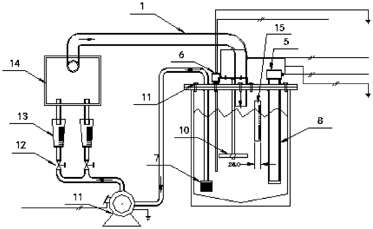
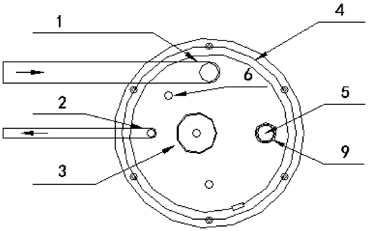
[0028] like figure 1 and figure 2 As shown, the present embodiment provides a kind of engine cylinder cavity electroplating equipment, is used for the electroplating of engine cylinder cavity, and this engine cylinder cavity electroplating equipment comprises the circulation pump 11 that connects in sequence, plating solution pumping pipe, frock Platform 14, plating solution inlet pipe 1, electroplating solution mother tank and liquid return pipe 2, the liquid inlet of the circulation pump 11 is connected with the liquid return pipe 2. The electroplating solution is circulated between the tooling platform 14 and the electroplating solution mother tank by the above-mentioned circulating pump 11, the above-mentioned plating solution pumping pipe, the plating solution inlet pipe 1 and the liquid return pipe 2 are the circulation pipelines of the electroplating solution, and the above-mentioned plating solution The model of the inlet pipe 1 is DN50PP, and the model of the liquid...


PUM

PropertyMeasurementUnit
angleaaaaaaaaaa

Abstract

The invention relates to the field of electroplating, and particularly provides inner cavity electroplating equipment of an engine cylinder body. The inner cavity electroplating equipment of the engine cylinder body comprises a circulating pump, a plating solution pump outlet pipe, a tooling table, a plating solution inlet pipe, a plating solution female groove and a liquid return pipe, wherein the circulating pump, the plating solution pump outlet pipe, the tooling table, the plating solution inlet pipe, the plating solution female groove and the liquid return pipe are sequentially connected,and the inlet of the circulating pump further communicates with the liquid return pipe. The tooling table is provided with an engine cylinder body clamping tool used for clamping an engine cylinder body. The plating solution female groove comprises a plating solution storage cavity, wherein the plating solution storage cavity is further provided with a stirring device. According to the inner cavity electroplating equipment of the engine cylinder body, plating solution circulates between the plating solution female groove and the tooling table through the circulating pump, and is stirred by the stirring device located in the plating solution female groove, so that insoluble substances in the plating solution can be uniformly distributed in the plating solution, thus preventing insoluble substances in the plating solution from being accumulated, and meanwhile the engine cylinder body with uniform plating, strong binding force and strong wear resistance can be easily obtained, and accordingly the service life of the engine cylinder body is prolonged.

Description

technical field [0001] The invention relates to the field of electroplating, in particular to an inner cavity electroplating equipment for electroplating the inner cavity of an engine cylinder. Background technique [0002] During the use of the engine block, its inner cavity is in a state of high temperature and frequent friction. In order to improve the service life of the engine block, a wear-resistant and high-temperature resistant material can be plated on the inner cavity of the engine block. The wear-resistant and high-temperature resistant material can be carbonized One or more of silicon, hard chrome or other materials. [0003] In order to electroplate the wear-resistant and high-temperature-resistant material for the inner cavity of the engine block, the engine block can be placed in the electroplating tank, but the overall electroplating of the engine block will inevitably cause certain waste in this way. It is also possible to put the electroplating solution in...

Claims


Application Information

Patent Timeline
Patent Type & Authority Applications(China)
IPC IPC(8): C25D21/10C25D21/02C25D17/02C25D5/02C25D7/04
CPCC25D5/02C25D7/04C25D17/02C25D21/02C25D21/10
Inventor 浦建堂周磊王晓谷松
Owner 山东鲁蓝环保科技有限公司
Learn More