Composite defect location method, device, equipment and storage medium

A compound positioning and defect technology, which is applied in the direction of measuring devices, cooperative operation devices, optical testing flaws/defects, etc., can solve problems such as difficulty in realization, and achieve the effect of reducing the difficulty of realization

Inactive Publication Date: 2022-03-04
BEIJING SHENZHOU TONGZHENG TECH
View PDF26 Cites 0 Cited by
  • Summary
  • Abstract
  • Description
  • Claims
  • Application Information

AI Technical Summary

Problems solved by technology

However, the above-mentioned positioning methods are more difficult to realize when performing defect positioning due to many external factors.

Method used


Image

  • Composite defect location method, device, equipment and storage medium
  • Composite defect location method, device, equipment and storage medium
  • Composite defect location method, device, equipment and storage medium

Examples


Embodiment Construction

[0064] Various exemplary embodiments, features, and aspects of the present disclosure will be described in detail below with reference to the accompanying drawings. The same reference numbers in the figures indicate functionally identical or similar elements. While various aspects of the embodiments are shown in drawings, the drawings are not necessarily drawn to scale unless specifically indicated.

[0065] The word "exemplary" is used exclusively herein to mean "serving as an example, embodiment, or illustration." Any embodiment described herein as "exemplary" is not necessarily to be construed as superior or better than other embodiments.

[0066] In addition, in order to better illustrate the present disclosure, numerous specific details are given in the following specific implementation manners. It will be understood by those skilled in the art that the present disclosure may be practiced without some of the specific details. In some instances, methods, means, componen...


PUM


Abstract

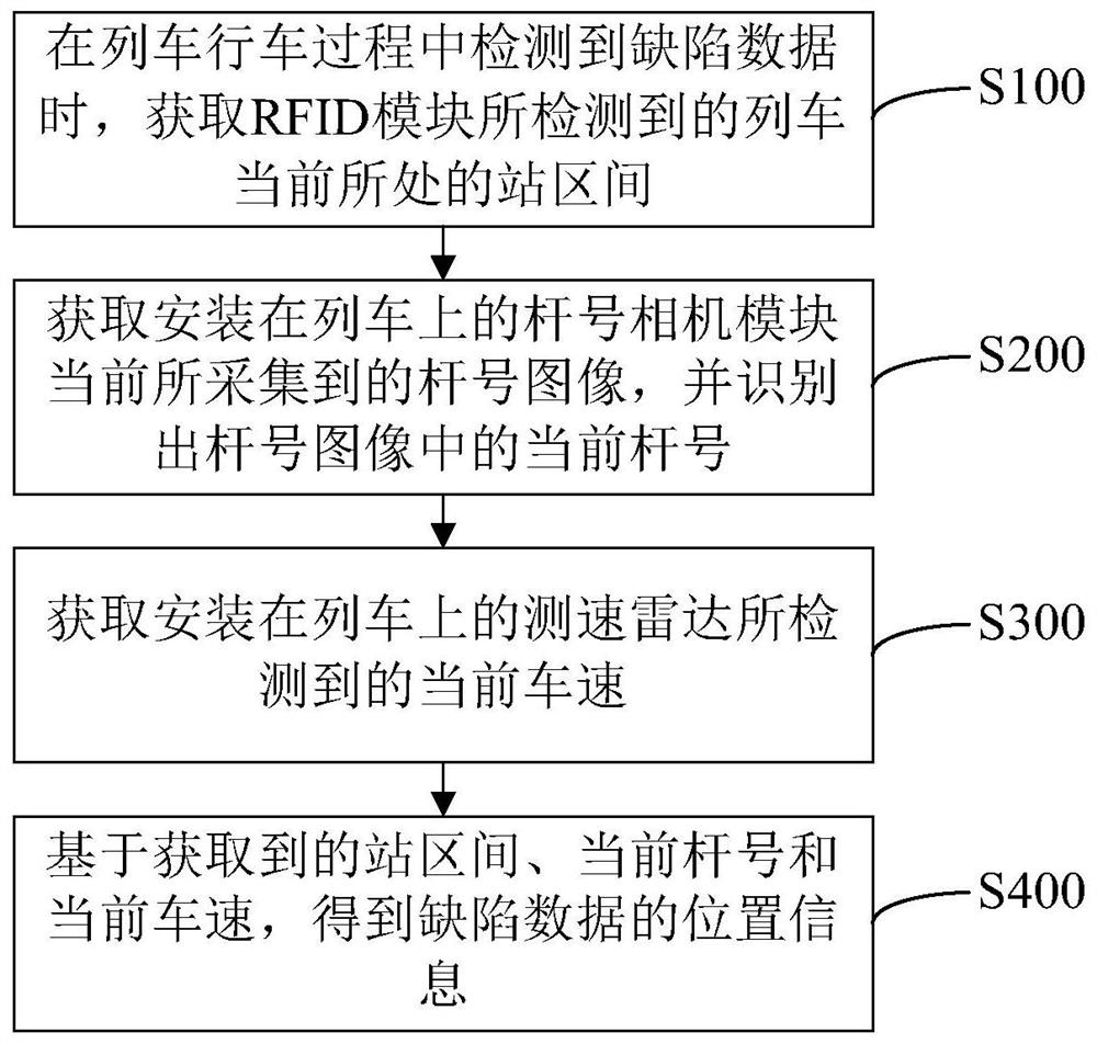
The present application relates to a defect composite positioning method, device, equipment and storage medium, wherein the method includes: when defect data is detected during train running, obtaining the station section where the train is currently located detected by the RFID module; The pole number image currently collected by the pole number camera module on the train recognizes the current pole number in the pole number image; obtains the current speed detected by the speed radar installed on the train; based on the acquired station interval, The current pole number and the current vehicle speed are used to obtain the position information of the defect data. Compared with the method of accessing the vehicle-mounted train control system used in the related art to locate defect data, it avoids the situation that the data interface of the vehicle-mounted train control system is not open to the third-party detection device and the defect location method cannot be realized. Thus, the implementation difficulty of the composite defect positioning method is effectively reduced.

Description

technical field [0001] The present disclosure relates to the technical field of transportation equipment, and in particular, to a defect compound location method and device, device and storage medium. Background technique [0002] The pantograph and catenary are the necessary power supply infrastructure on the subway line. If the initial defects are not found and dealt with in time, pantograph-catenary accidents may occur and seriously affect the safe operation of the subway. In order to quickly detect the health status of pantograph-catenary operation, the current detection schemes choose to install the equipment on special detection vehicles and running subway electric buses. However, a positioning method is needed for the detected defect data to determine its specific position on the physical circuit. [0003] In the related technology, it is usually used to access the on-board train control system, install a shaft end encoder, or use image recognition to realize the loc...

Claims


Application Information

Patent Timeline
Patent Type & Authority Patents(China)
IPC IPC(8): G01N21/01G01N21/88G06K17/00G06T7/00G06V20/54
CPCG06T7/0004G01N21/01G01N21/8851G06K17/0029G01N2021/0112G01N2021/8887G06V20/54
Inventor 林菲吴宽韩国涛李永光
Owner BEIJING SHENZHOU TONGZHENG TECH
Why Eureka
Try Eureka