
Insect trap

A trap and insect technology, applied in the field of insect traps, can solve the problems of low pest killing efficiency and high escape rate, achieve good trapping effect, improve trapping efficiency, and prevent escape

Pending Publication Date: 2019-10-22
洪德强
View PDF1 Cites 0 Cited by
  • Summary
  • Abstract
  • Description
  • Claims
  • Application Information

AI Technical Summary

Problems solved by technology

However, because the trapped pests are easy to climb from the inner wall of the insect collecting bottle and return to escape from the trapping channel, the escape rate is relatively high, and the pest killing efficiency is low.

Method used


Image

  • Insect trap
  • Insect trap
  • Insect trap

Examples


Embodiment 1

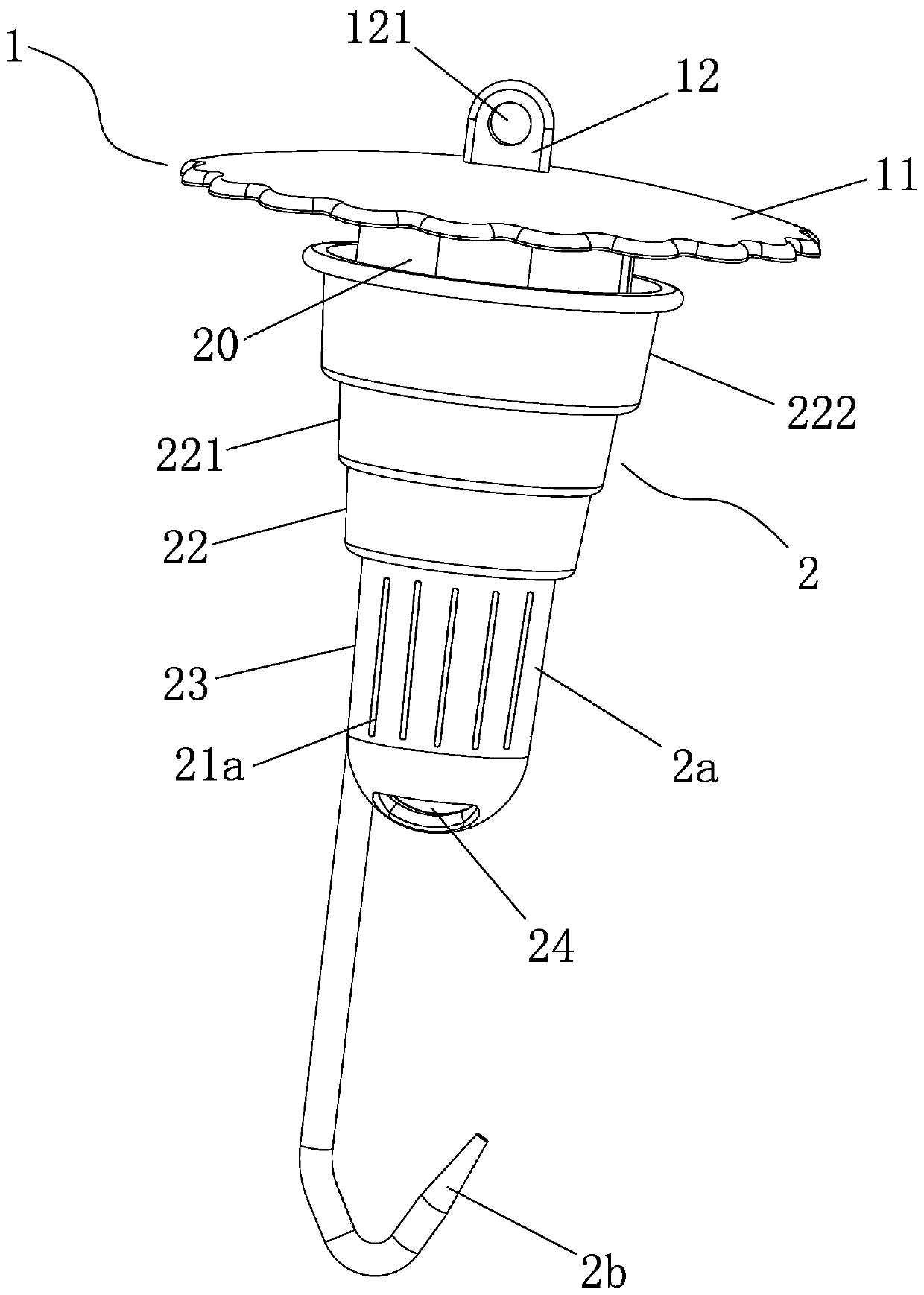
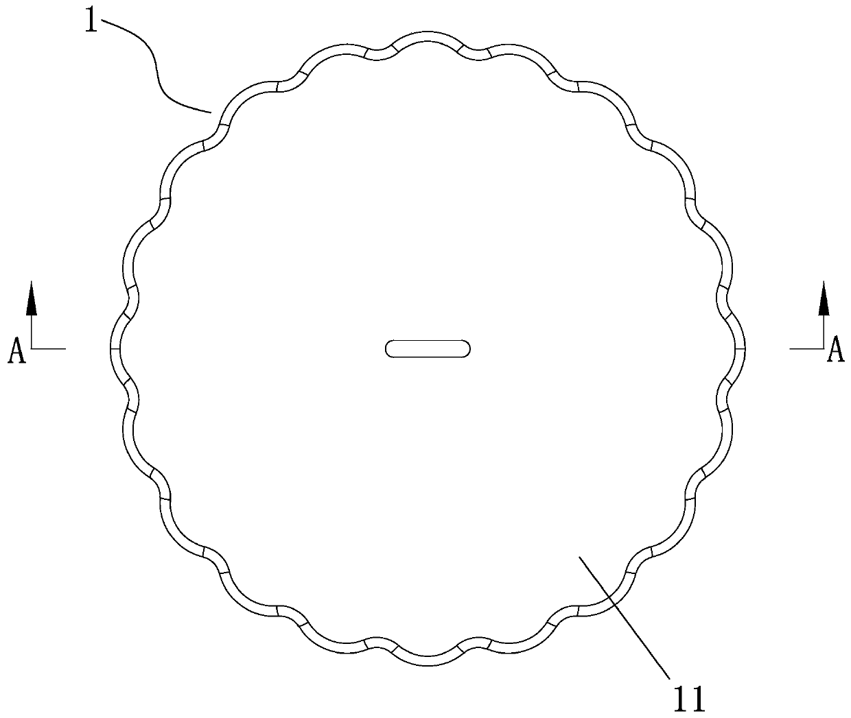
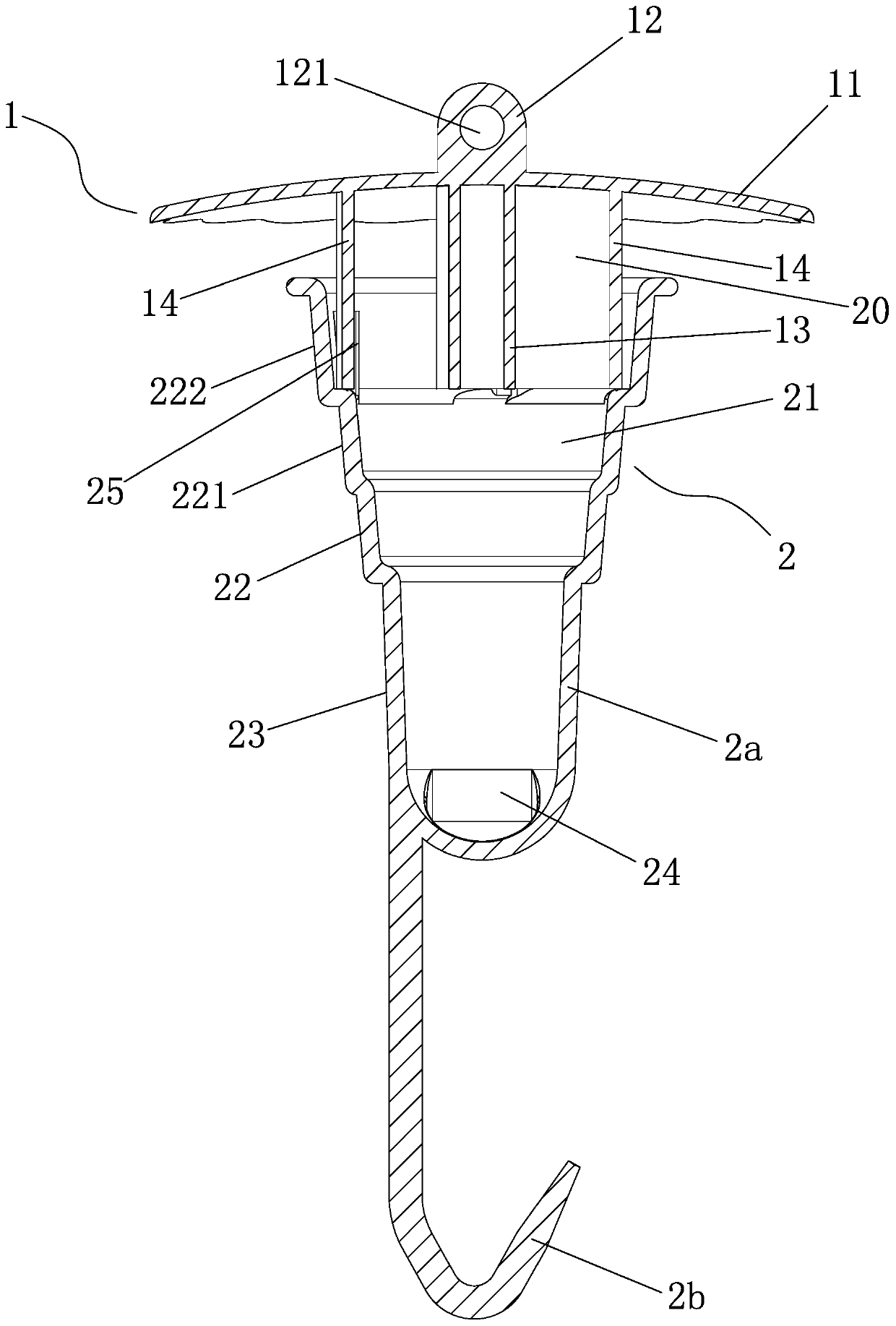
[0029] Embodiment one, Figure 1 to Figure 6 As shown, an insect trap is used in conjunction with an insect collecting bottle 10, and includes a cover 1 and a connecting cylinder 2. The upper end of the connecting cylinder 2 is provided with a cavity 21, and the cover 1 is fixedly connected to the connecting cylinder 2. In the upper part, four insect trapping passages 20 communicating with the concave cavity 21 are formed between the cover body 1 and the connecting cylinder 2, and the outer side of the connecting cylinder 2 is provided with a fitting that can plug the inner surface of the mouth of the insect collecting bottle 10. Outer peripheral surface 22, the said matching outer peripheral surface 22 is an inverted tapered surface, and the cylinder outer surface 23 below the matching outer peripheral surface 22 is provided with two worm-injecting through-holes 24 communicating with the concave cavity 21 and the outside of the connecting cylinder 2. When the outer peripheral...

Embodiment 2

[0039] Embodiment two, Figure 7 to Figure 10 Shown, an insect trap. The difference from Embodiment 1 is that the matching structure is a mounting column 2c extending downward from the outer surface 23 of the column, and the lower end of the mounting column 2c is provided with a mounting concave hole 2d. The installation concave hole 2d is used for inserting the insect lure 3 . The insect lure 3 is a rod-shaped lure, and the rod-shaped lure is adsorbed with insect sex pheromone. Part of the ventilation hole 21a is integrated with the insect-entrying through hole 24, and the volatilization path of the insect pheromone is more direct, which further improves the volatilization speed of the insect lure 3 and improves the trapping efficiency.

[0040] The use mode of this embodiment is the same as that of this embodiment one. Utilize the matching outer peripheral surface 22 and the bottleneck inner surface of the insect collecting bottle 10 to plug and cooperate to form a solid c...


PUM


Abstract

The invention discloses an insect trap for use with an insect-collecting bottle. The insect trap comprises a cover, and a connection post. The upper end of the connection post is provided with a cavity. The cover is fixedly connected with the upper portion of the connection post; at least one trap passage communicated with the cavity is formed between the cover and the connection post; the outer side of the connection post is provided with a fitting peripheral face which may block the inner surface of an opening of the insect-collecting bottle; the outer face of the connection post below the fitting peripheral face is provided with at least one insect-incoming through hole by which the cavity is communicated with the outside of the connection post; when the inner surface of the opening ofthe insect-collecting bottle is blocked with the fitting peripheral face, a trapped insect enters the insect-collecting bottle through the insect-incoming through hole; the outer face of the connection post below the fitting peripheral face is provided with a fitting structure which is used to mount an insect lure. Preferably the fitting structure is a hook extended down from the outer face of theconnection post or a mounting post extended down; the lower end of the mounting post is provided with a mounting hole. The insect trap has the advantages that insect escaping is prevented effectively, trapping efficiency is improved, and the insect trap is convenient to mount and use.

Description

technical field [0001] The invention relates to the technical field of insect control equipment manufacture, in particular to an insect trap. Background technique [0002] Nowadays, in the technical field of pest control of crops, insect traps and insect traps such as insect sex pheromones have been widely used to hunt and kill insects, which has been proved to be a green and effective management method. Therefore various insect traps have occurred on the market. [0003] For example, on September 08, 2017, a Chinese invention patent with the patent number ZL201621272011.6 and the name "A Threaded Insect Trapper" was published, including a connecting cylinder, and an insect trapping channel was arranged on the top of the connecting cylinder. The bottom of the cylinder is a buffer inner cavity, and the trapping channel and the buffering inner cavity are connected through the inlet pipe, and the buffering inner cavity is connected to the threaded bottle through a threaded por...

Claims


Application Information

Patent Timeline
Patent Type & Authority Applications(China)
IPC IPC(8): A01M1/02
CPCA01M1/02
Inventor 洪德强
Owner 洪德强
Features
  • Generate Ideas
  • Intellectual Property
  • Life Sciences
  • Materials
  • Tech Scout
  • Unparalleled Data Quality
  • Higher Quality Content
  • 60% Fewer Hallucinations
Learn More