Method and system for constructing driving coordinate system

A construction method and coordinate system technology, applied in the construction method and system field of the driving coordinate system, can solve the problems that can not truly reflect the relative relationship, and achieve the effect of accurate distance information

Active Publication Date: 2021-06-22
毫末智行科技有限公司
View PDF5 Cites 0 Cited by
  • Summary
  • Abstract
  • Description
  • Claims
  • Application Information

AI Technical Summary

Problems solved by technology

[0005] In view of this, the present invention aims to propose a method for constructing a driving coordinate system to solve the problem that the vehicle coordinate system cannot truly reflect the relative relationship between the vehicle and the surrounding environment

Method used


Image

  • Method and system for constructing driving coordinate system
  • Method and system for constructing driving coordinate system
  • Method and system for constructing driving coordinate system

Examples


Embodiment 1

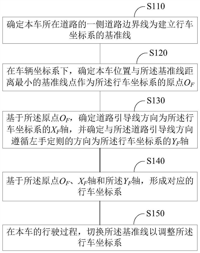
[0036] figure 1 It is a schematic flowchart of a method for constructing a driving coordinate system in Embodiment 1 of the present invention, wherein the method for constructing a driving coordinate system is used to establish a new vehicle, The driving coordinate system of the mapping relationship between the target and the road. In order to more clearly describe the definition and construction method of the driving coordinate system in the embodiment of the present invention, the global coordinate system and the vehicle coordinate system commonly used in vehicle automatic driving are described here first.

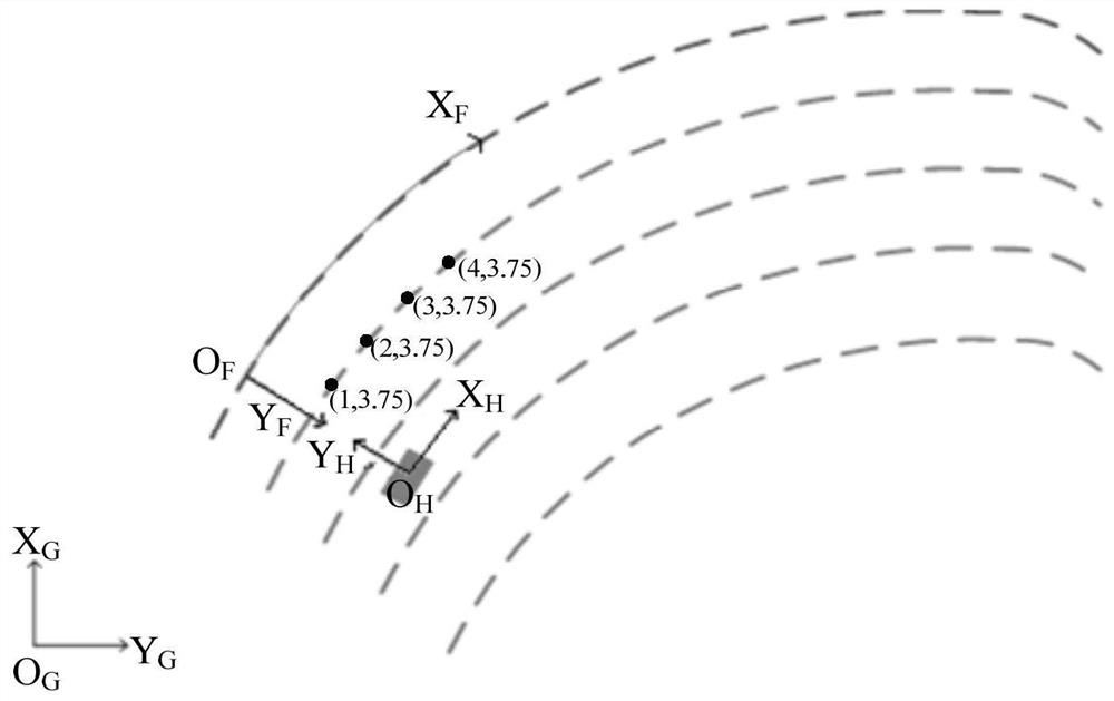
[0037] Among them, the global coordinate system X G o G Y G Based on the earth coordinate system, X G pointing north, Y G Pointing to the east, the angle direction is positive clockwise, and the angle range is [0, 360°]. Among them, the map lane line information and the like are given based on the global coordinate system.

[0038] Vehicle coordinate system X H o...

Embodiment 2

[0070] Figure 8 It is a schematic structural diagram of a driving coordinate system construction system according to Embodiment 2 of the present invention. The driving coordinate system construction system is based on the same inventive idea as the driving coordinate system construction of the above-mentioned embodiment. Such as Figure 8 As shown, the driving coordinate system construction system may include: a reference line determination module 810, which is used to determine the road boundary line on one side of the road where the vehicle is located as the reference line for establishing the driving coordinate system; the origin determination module 820, in the vehicle coordinate system Next, determine the reference line point with the smallest distance between the position of the vehicle and the reference line as the origin O of the driving coordinate system F ; Coordinate axis determination module 830, for based on the origin O F , determine the direction of the road ...


PUM


Abstract

The invention relates to the field of intelligent transportation, and provides a method and system for constructing a driving coordinate system. The driving coordinate system construction method of the present invention includes: determining the road boundary line on one side of the road where the vehicle is located as the reference line for establishing the driving coordinate system; The datum line point is taken as the origin O of the driving coordinate system F ; based on the origin O F , determine the direction of the road guiding line as the X of the driving coordinate system F axis, and determine the direction that follows the left-hand rule with the direction of the road guiding line as the Y of the driving coordinate system F axis; and based on the origin O F 、X F axis and the Y F axis to form the corresponding driving coordinate system. The driving coordinate system established by the present invention is especially suitable for curved road conditions. It uses the longitudinal arc length to represent the longitudinal distance of road targets. Compared with the straight-line distance in the vehicle coordinate system, it can more realistically express the vehicle and road targets. the distance between.

Description

technical field [0001] The invention relates to the field of intelligent transportation, in particular to a method and system for constructing a driving coordinate system. Background technique [0002] At present, vehicles with an autonomous driving system (ADS for short) have begun to be gradually introduced to the market, which has greatly promoted the development of intelligent transportation. ADS uses a variety of sensing devices installed on the vehicle to collect lane line data around the vehicle and road target (such as other vehicles in front, also known as targets) data in real time to identify the static and dynamic characteristics of the target and determine the target. The position on the road, so that the automatic driving computer can judge the potential danger in the shortest time, and take effective measures to prevent the danger from happening. [0003] Therefore, it can be seen that determining valid information on the road such as lane line data and road ...

Claims


Application Information

Patent Timeline
Patent Type & Authority Patents(China)
IPC IPC(8): G01C21/34
CPCG01C21/343
Inventor 葛建勇张凯韩汝涛高健崔文锋甄龙豹刘宏伟王天培
Owner 毫末智行科技有限公司
Why Eureka
Try Eureka