Gate for rail transit and control method

A technology for rail transit and turnstiles, applied in instruments, ticketing equipment, time registers, etc., can solve the problems of frequent gate movements, increase maintenance costs, shorten the life of turnstiles, etc., to shorten the waiting time for entry and exit, and the maintenance cost. Reduce and improve the effect of passing ability

Pending Publication Date: 2019-10-22
SHANGHAI UNIV OF ENG SCI
View PDF2 Cites 1 Cited by
  • Summary
  • Abstract
  • Description
  • Claims
  • Application Information

AI Technical Summary

Problems solved by technology

[0004] In the scenario of rail transit application, the passenger flow is huge, the gates of the gates operate frequently, and the utilization rate is extremely high. During the peak period of passenger flow, they are in continuous and uninterrupted opening and closing actions, and the da

Method used


Image

  • Gate for rail transit and control method
  • Gate for rail transit and control method
  • Gate for rail transit and control method

Examples


Example Embodiment

[0031] Example one

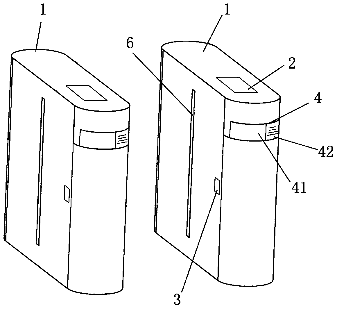
[0032] Such as figure 1 As shown, this embodiment provides a gate for rail transit, which includes a plurality of gate case bodies 1 arranged side by side. A controller 2, an infrared sensor 3, an alarm 4 and a light curtain device 6 are arranged on each gate case body 1.

[0033] A light curtain device 6 is provided on one side of the gate case body 1, and the light curtain device 6 is arranged in the center of the side wall of the gate case body 1. The light curtain device 6 is a plurality of vertically arranged laser emitters that can emit colored laser beams. The laser beams are arranged laterally side by side to form a visible light curtain wall 7 between two adjacent gate cabinet bodies 1. A laser receiver can also be provided on the other side of the gate case body 1 to prevent the laser beam from being scattered.

[0034] The controller 2 is installed on the top of the gate case body 1 for ticket checking. The controller 2 can also be equipped with an ...

Example Embodiment

[0038] Example two

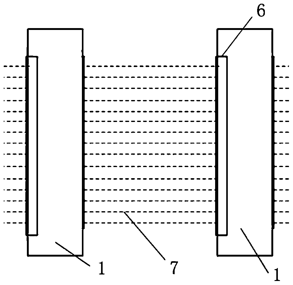
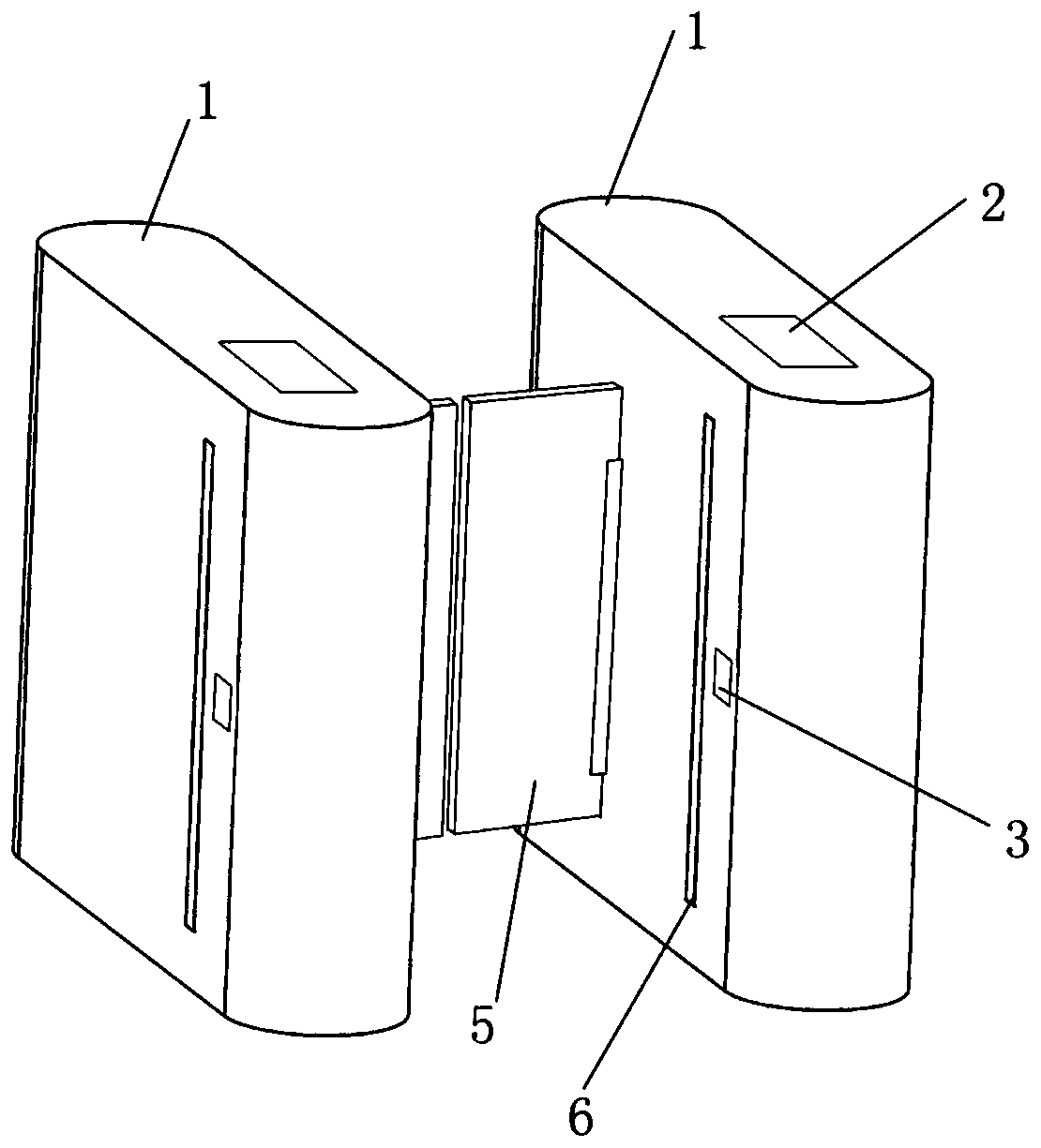
[0039] Such as figure 2 As shown, this embodiment provides a gate for rail transit, which includes a plurality of gate case bodies 1 arranged side by side. A controller 2, an infrared sensor 3, a gate 5 and a light curtain device 6 are provided on each gate case body 1. In this embodiment, a light curtain device 6 is added to the existing gate.

[0040] The gate 5 adopts the same mechanical mechanism as the traditional gate 5 and is arranged between two adjacent gate case bodies 1 and in the center of the side wall of the gate case body 1. A light curtain device 6 is provided on one side of the gate case body 1, and the light curtain device 6 is arranged at the front or rear end of the side wall of the gate case body 1, subject to the passing direction of pedestrians, and the light curtain device 6 is arranged on the gate 5. The front.

[0041] The light curtain device 6 is a plurality of vertically arranged laser emitters that can emit colored laser beams. ...

Example Embodiment

[0047] Example three

[0048] This embodiment provides a gate for rail transit, which includes a plurality of gate case bodies arranged side by side. A controller, an infrared sensor, an alarm, a gate and a light curtain device are arranged on the body of each gate case. This embodiment is a combination of the first embodiment and the second embodiment, that is, both a light curtain device and an alarm are added to the existing gate, and its specific structure will not be repeated.

[0049] The workflow of this embodiment is as Figure 4 Shown:

[0050] Step S1, the initial (default) state of the gate is: the gate is open (passing state), the light curtain wall is on (blocking state), the LED light of the alarm is off; waiting for swiping;

[0051] Step S2, payment methods such as pedestrian swiping cards trigger the gate controller;

[0052] In step S3, the controller judges whether the traffic conditions are met, if the conditions are met, go to S4, and if the conditions are not me...


PUM


Abstract

The invention relates to a gate for rail transit. The gate comprises a plurality of gate case bodies arranged side by side; each gate case body is provided with a controller and an infrared sensor; the gate further comprises an abnormal execution mechanism connected with the controller; a light curtain device is arranged at one side of each gate case body; and the light curtain devices form a visible light curtain wall between every two adjacent gate case bodies. According to the gate for rail transit of the invention, mechanical opening and closing actions are greatly reduced; a blocking effect can still be achieved visually; the occurrence of behaviors such as ticket evasion is prevented through the abnormal execution mechanism; and therefore, the gate has greatly-improved reliability and usability compared with the prior art. The actions of mechanical parts of the gate are reduced largely, and therefore, the service life of the gate is prolonged, and the maintenance cost of the gateis also remarkably reduced.

Description

technical field [0001] The invention relates to a gate, in particular to a gate for rail transit and a control method. Background technique [0002] The gate (automatic ticket gate AG) is the ticket checking device for rail transit pedestrians entering and exiting the station. [0003] Disclosed a kind of subway gate machine as Chinese invention CN207934789U, adopts the structure of tripod gate to realize passage. Chinese invention CN201820040567.5 discloses a subway security inspection gate, which realizes the functions of security inspection and ticket inspection at the same time through two gates provided. It can be seen that the blocking bodies and blocking methods of the current gates adopt physical structures such as swing gates, translational gates, wing gates, etc., and the opening and closing functions are realized by controlling the mechanical action of the gates by motors. When the gate is in use, under normal conditions, the blocking body is closed. Only when p...

Claims


Application Information

Patent Timeline
IPC IPC(8): G07C9/00G07B11/00
CPCG07B11/00G07C9/20
Inventor 马子彦马程前刘浪顾晓菡
Owner SHANGHAI UNIV OF ENG SCI
Why Eureka
Try Eureka