Supercharge Your Innovation With Domain-Expert AI Agents!

Core-pulling mechanism of injection mold and injection mold

A technology for injection molds and core-pulling mechanisms, applied in the field of injection mold core-pulling mechanisms and injection molds with such core-pulling mechanisms, can solve the problems of increasing the difficulty of mold design and production, increasing production costs, defective products, etc., to reduce The difficulty of mold design and production, the effect of improving the yield rate and simple structure

Pending Publication Date: 2019-10-25
李代坤
View PDF0 Cites 0 Cited by
  • Summary
  • Abstract
  • Description
  • Claims
  • Application Information

AI Technical Summary

Problems solved by technology

However, if figure 2 As shown, during injection molding in this way, the stepped structure 401 of the row position will be retreated by the relatively large injection pressure from the injection molding machine, and the size of the injection pressure depends on the shape of the product, the stress area of ​​the row position and the injection molding pressure. The required molding conditions (friction force and molding conditions cannot be calculated, can only be estimated), so it is impossible to calculate the pressure on the retreat of the row position, and it is possible that the molding conditions change slightly during the injection molding process This causes the row position to recede. Therefore, the existing structure cannot guarantee that the row position will not retreat or loosen due to the pressure given by the injection molding machine during the injection molding and pressure holding process.
As long as the distance of row position retreat is greater than 0.02mm, the molten plastic liquid will flow into the gap caused by the retreat or loosening of the row position, thereby causing flash 202 in the sink hole of the product and making the steps of the sink hole The surface 203 becomes thick or protruding, resulting in defective products and reducing the yield of injection molding
The existing repair of the above problems can only be done through accurate design calculations and a large number of tests and modifications, which greatly increases the difficulty of mold design and production and increases production costs.

Method used


Image

  • Core-pulling mechanism of injection mold and injection mold
  • Core-pulling mechanism of injection mold and injection mold
  • Core-pulling mechanism of injection mold and injection mold

Examples


Embodiment Construction

[0023] In order to describe the technical content, structural features, and achieved effects of the present invention in detail, the following will be described in detail in conjunction with the embodiments and accompanying drawings.

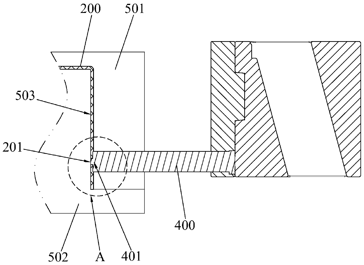
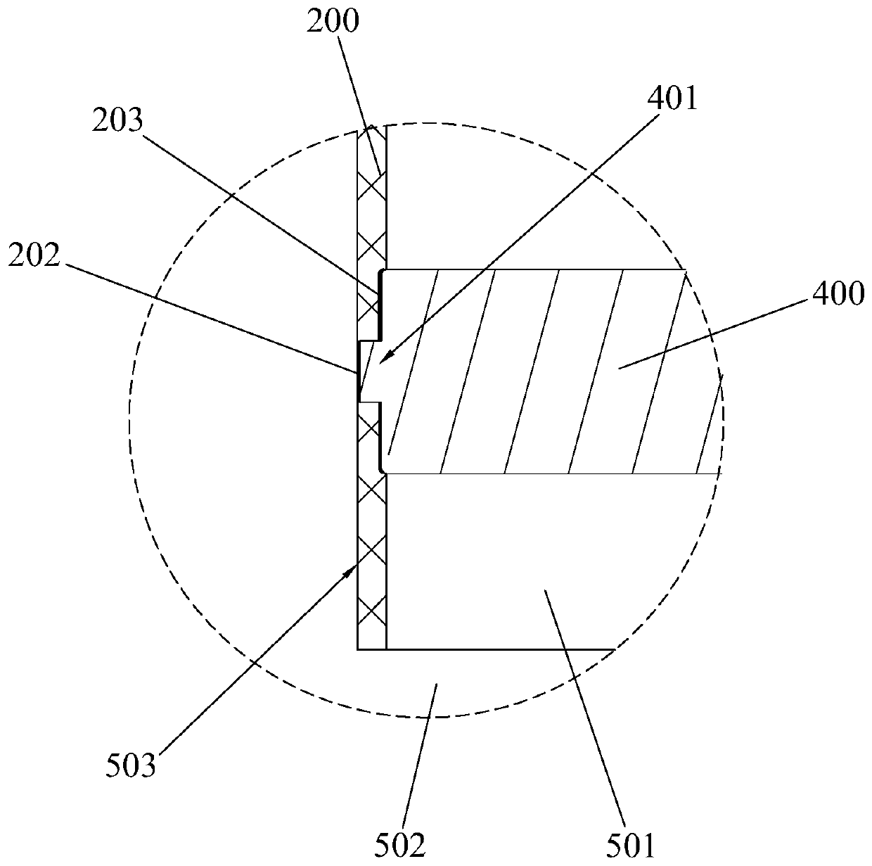
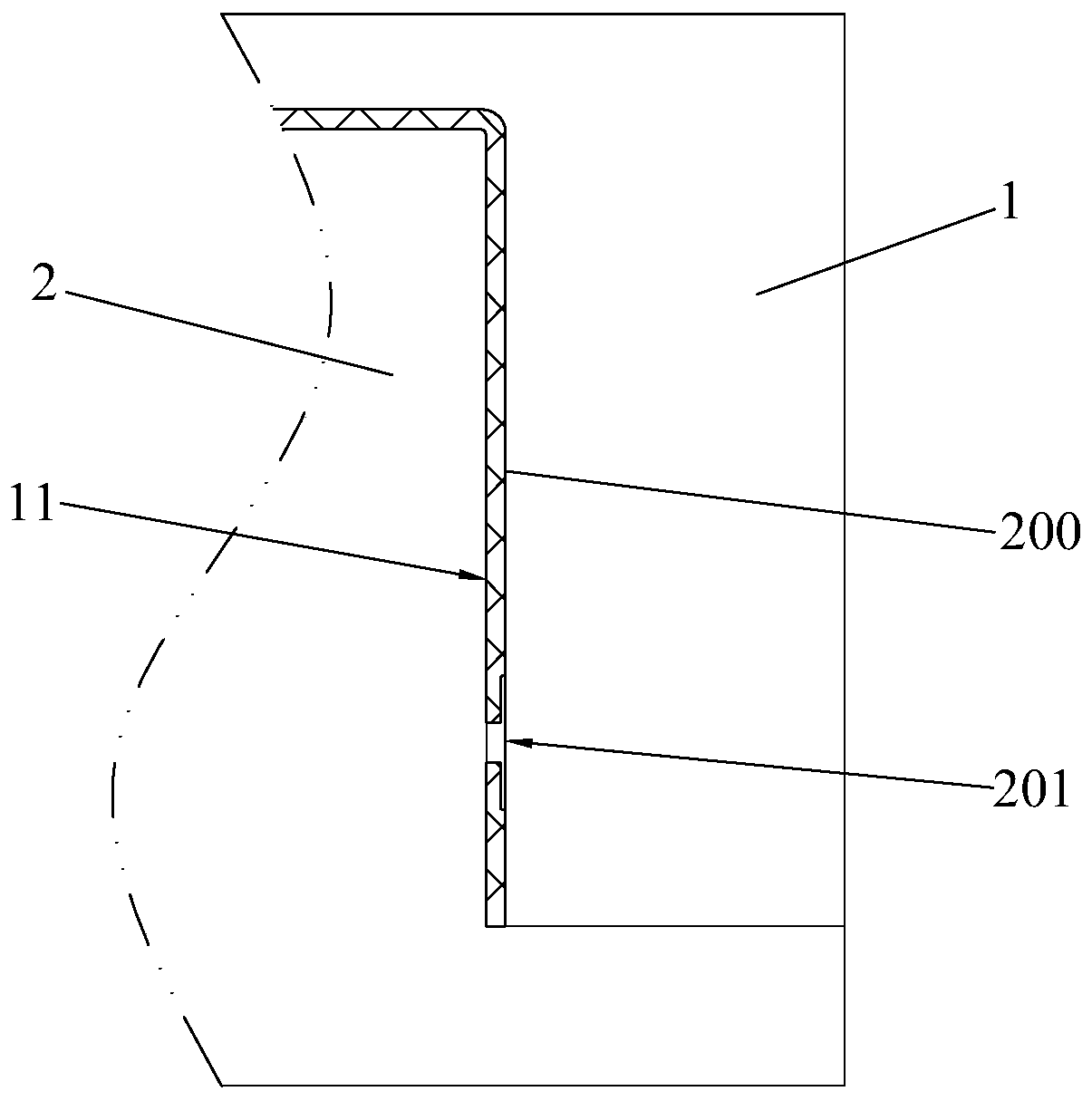
[0024] Such as image 3 , Figure 4 and Figure 5 As shown, the injection mold 100 of the present invention can form a sinkhole 201 in the process of molding a plastic product 200, which includes a front mold core 1, a rear mold core 2, a guide block 3, an injection mold core pulling mechanism 4 and a driving device 5. A cavity 11 is formed between the front mold core 1 and the rear mold core 2 , and the injection mold core pulling mechanism 4 includes a first row position 41 , a second row position 42 , an elastic element 43 and a row position seat 44 . The front ends of the first row 41 and the second row 42 extend into the cavity 11, and the front ends of the second row 42 are against the inner surface of the cavity 11; Seat 44 is provided...


PUM


Abstract

The invention discloses a core-pulling mechanism of an injection mold. The core-pulling mechanism is used for forming a sinking hole and comprises a first motion station, a second motion station, an elastic element and a motion station seat. The second motion station is sleeved in the first motion station in a sliding manner, the front end of the second motion station stretches out of the front end of the first motion station, the front end of the first motion station is used for forming a large hole of the sinking hole, and the front end of the second motion station is used for forming a through hole of the sinking hole. The first motion station is provided with a first limiting portion, the second motion station is provided with a second limiting portion, and the first limiting portion and the second limiting portion are spaced by a certain gap in the work state. The rear end of the first motion station and the motion station seat are fixed. The elastic element provides elastic forceenabling the front end of the second motion station to stretch out of the front end of the first motion station. According to the core-pulling mechanism of the injection mold, flashes can be effectively prevented from being generated during injection molding of the sinking hole, the injection molding yield can be improved, and the difficulty and cost of mold design and manufacturing can be reduced. In addition, the invention discloses the injection mold.

Description

technical field [0001] The invention relates to an injection mold, in particular to a core-pulling mechanism of an injection mold and an injection mold with the core-pulling mechanism. Background technique [0002] In injection molding, it is often necessary to process a sink hole 201 on the product 200, such as figure 1 As shown, the existing method is to design a step structure 401 corresponding to the sinkhole 201 on a row position 400, and extend the step structure 401 into the cavity 503 of the mold composed of the front mold core 501 and the rear mold core 502 Inside, the oil cylinder is used to drive the movement of the position, so that the sink hole 201 is formed after injection molding. However, if figure 2 As shown, during injection molding in this way, the stepped structure 401 of the row position will be retreated by the relatively large injection pressure from the injection molding machine, and the size of the injection pressure depends on the shape of the p...

Claims


Application Information

Patent Timeline
Patent Type & Authority Applications(China)
IPC IPC(8): B29C45/44B29C45/33
CPCB29C45/44B29C45/332
Inventor 李代坤
Owner 李代坤
Features
  • R&D
  • Intellectual Property
  • Life Sciences
  • Materials
  • Tech Scout
  • Unparalleled Data Quality
  • Higher Quality Content
  • 60% Fewer Hallucinations
Learn More