Supercharge Your Innovation With Domain-Expert AI Agents!

Air-tightness detection equipment for oil-cooled tube assembly

A technology of air tightness detection and oil cooling tube, which is applied in the direction of fluid tightness test, liquid tightness measurement using liquid/vacuum degree, measuring device, etc., which can solve the problem that workers cannot approach, waste time, and low detection efficiency and other problems to achieve the effect of avoiding false detection of workpieces, improving detection efficiency, and improving efficiency

Active Publication Date: 2017-05-31
朗安(天津)科技发展有限公司
View PDF0 Cites 3 Cited by
  • Summary
  • Abstract
  • Description
  • Claims
  • Application Information

AI Technical Summary

Problems solved by technology

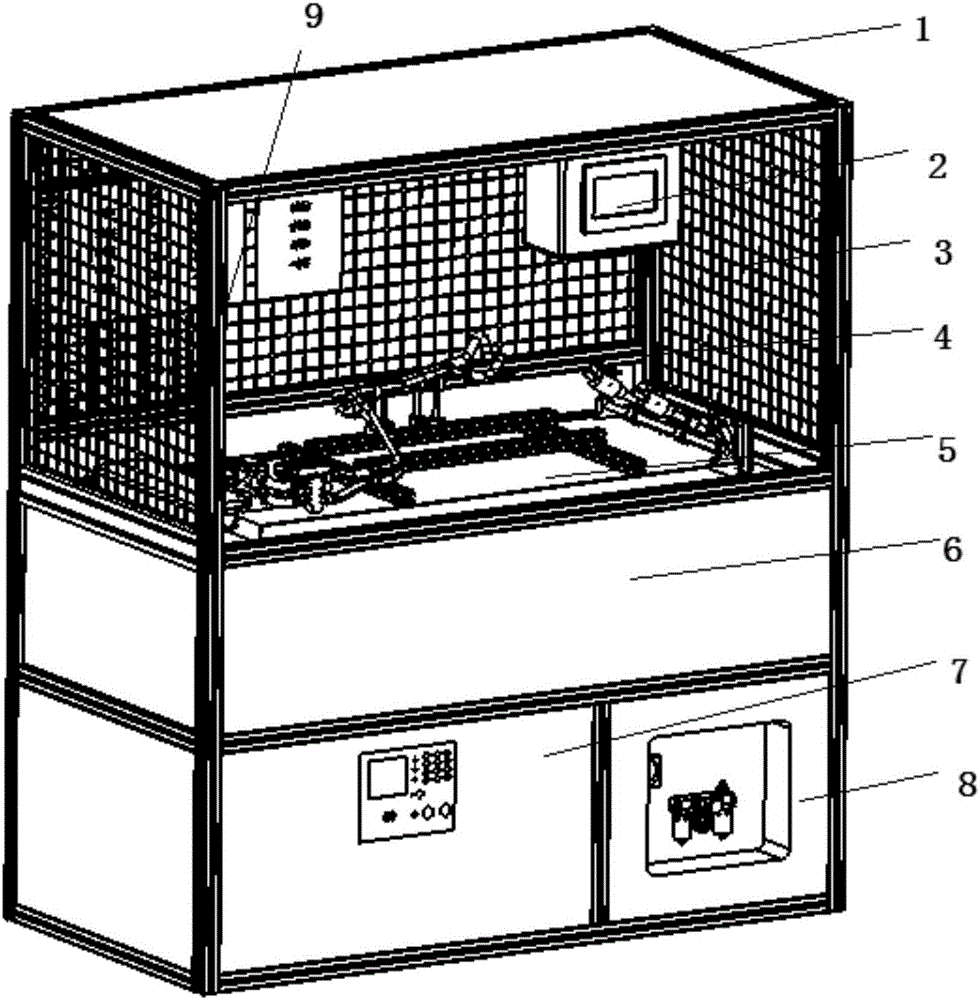
[0002] With the improvement of people's living standards, cars have gradually become the main means of transportation and the choice of daily travel. The demand for cars is gradually increasing. The operation will inevitably generate a lot of heat. In order to improve the service life of the engine, it is often connected to the cooling system through the oil cooling pipe to dissipate heat. Therefore, it is necessary to ensure the airtightness of the oil cooling pipe assembly. The air tightness test of the pipe assembly can only be tested individually. For the safety of the staff and to prevent the oil pipe from bursting, it is often necessary for the staff not to approach during the test. After the test is completed, a new workpiece can be replaced for testing. Low cost, waste of time, in view of this situation, the present invention proposes a kind of air tightness testing equipment for oil cooling pipe assembly, by setting a turning mechanism in the equipment, the clamping and fixing of the workpiece and the air tightness testing are separated, and the double station is realized The uninterrupted loading, unloading and testing greatly saves the testing time, improves the efficiency, and is safe and reliable, which ensures the safety performance of the testing and improves the testing efficiency. Reduced testing costs

Method used


Image

  • Air-tightness detection equipment for oil-cooled tube assembly
  • Air-tightness detection equipment for oil-cooled tube assembly
  • Air-tightness detection equipment for oil-cooled tube assembly

Examples


Embodiment Construction

[0035] It should be noted that, in the case of no conflict, the embodiments of the present invention and the features in the embodiments can be combined with each other.

[0036] In describing the present invention, it should be understood that the terms "center", "longitudinal", "transverse", "upper", "lower", "front", "rear", "left", "right", " The orientations or positional relationships indicated by "vertical", "horizontal", "top", "bottom", "inner" and "outer" are based on the orientations or positional relationships shown in the drawings, and are only for the convenience of describing the present invention and Simplified descriptions, rather than indicating or implying that the device or element referred to must have a particular orientation, be constructed and operate in a particular orientation, and thus should not be construed as limiting the invention. In addition, the terms "first", "second", etc. are used for descriptive purposes only, and should not be understood ...


PUM


Abstract

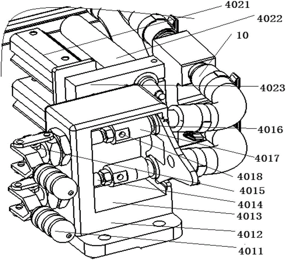
The invention provides air-tightness detection equipment for an oil-cooled tube assembly. The air-tightness detection equipment comprises a frame body, a turnover mechanism, an explosion-proof tank and a control box, wherein the turnover mechanism, the explosion-proof tank and the control box are arranged on the frame body in layers from top to bottom; the turnover mechanism comprises a turnover plate rotationally connected with the frame body; and detection tools are arranged on mirror images at the upper side and the lower side of the turnover plate. According to the air-tightness detection equipment for the oil-cooled tube assembly, the turnover mechanism is arranged in the equipment, and workpiece clamping and fixing are separated from air-tightness detection, so that uninterrupted disassembly and detection of double stations can be achieved, the detection time is greatly shortened, the efficiency is improved, the air-tightness detection equipment is safe and reliable, the detection efficiency is improved while the detection security is ensured, the air-tightness detection equipment is suitable for a lot of detection during massive production of the oil-cooled tube assembly, the time is shortened and the detection cost is reduced.

Description

technical field [0001] The invention belongs to the field of airtightness detection of automobile parts, in particular to an airtightness detection device for an oil cooling pipe assembly. Background technique [0002] With the improvement of people's living standards, cars have gradually become the main means of transportation and the choice of daily travel. The demand for cars is gradually increasing. The operation will inevitably generate a lot of heat. In order to improve the service life of the engine, it is often connected to the cooling system through the oil cooling pipe to dissipate heat. Therefore, it is necessary to ensure the airtightness of the oil cooling pipe assembly. The air tightness test of the pipe assembly can only be tested individually. For the safety of the staff and to prevent the oil pipe from bursting, it is often necessary for the staff not to approach during the test. After the test is completed, a new workpiece can be replaced for testing. Low ...

Claims


Application Information

Patent Timeline
Patent Type & Authority Applications(China)
IPC IPC(8): G01M3/28
CPCG01M3/2815
Inventor 刘训省喻坚孙刚
Owner 朗安(天津)科技发展有限公司
Features
  • R&D
  • Intellectual Property
  • Life Sciences
  • Materials
  • Tech Scout
  • Unparalleled Data Quality
  • Higher Quality Content
  • 60% Fewer Hallucinations
Learn More