
Pneumatic conveying pipeline air supply device

A technology for pneumatic conveying pipelines and air replenishers, which is applied to conveyors, conveying bulk materials, transportation and packaging, etc., can solve problems such as leakage of air replenishers in pipelines, backflow of conveyors, etc., and achieve good air replenishment effect and structure Simple, good effect of invigorating Qi

Pending Publication Date: 2019-10-25
浙江管工智能机械设备有限公司
View PDF1 Cites 1 Cited by
  • Summary
  • Abstract
  • Description
  • Claims
  • Application Information

AI Technical Summary

Problems solved by technology

The above-mentioned structure cannot solve the problems of air leakage and backflow of the conveyor during the air supply process of the pipeline air supply device, and does not provide effective technical inspiration for solving the above technical problems

Method used


Image

  • Pneumatic conveying pipeline air supply device
  • Pneumatic conveying pipeline air supply device

Examples


Embodiment 1

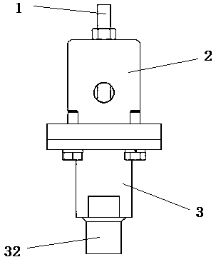
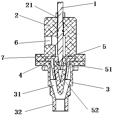
[0031] A pneumatic conveying pipeline gas supplement, comprising a thimble 1, an upper shell 2, a lower shell 3, a gas buffer portion 4 and a thimble base 5, and the lower end of the upper shell 2 is connected with the upper end of the lower shell 3, so the The upper casing 2 is provided with an air inlet 6, and the upper end of the upper casing 2 is provided with an opening 21 for the ejector pin 1 to pass through. A thimble base 5 is arranged below the air inlet 6 and the thimble 1 , and a gas buffer 4 is sleeved on the outside of the thimble base 5 .

[0032] In the above structure, the gas enters the pneumatic conveying pipeline gas insulator through the air inlet 6. When the gas enters, the ejector pin 1 lifts up to make the gas smoothly enter the air inlet 6, fills the air inlet 6 and the ejector pin base 5, and presses the ejector pin 1 downward. , compress the gas in the air inlet 6 and the thimble base 5, so that the gas pressure in the inflator increases, and after t...

Embodiment 2

[0048] A pneumatic conveying pipeline gas supplement, comprising a thimble 1, an upper shell 2, a lower shell 3, a gas buffer portion 4 and a thimble base 5, and the lower end of the upper shell 2 is connected with the upper end of the lower shell 3, so the The upper casing 2 is provided with an air inlet 6, and the upper end of the upper casing 2 is provided with an opening 21 for the ejector pin 1 to pass through. A thimble base 5 is arranged below the air inlet 6 and the thimble 1 , and a gas buffer 4 is sleeved on the outside of the thimble base 5 .

[0049] In the above structure, the gas enters the pneumatic conveying pipeline gas insulator through the air inlet 6. When the gas enters, the ejector pin 1 lifts up to make the gas smoothly enter the air inlet 6, fills the air inlet 6 and the ejector pin base 5, and presses the ejector pin 1 downward. , compress the gas in the air inlet 6 and the thimble base 5, so that the gas pressure in the inflator increases, and after t...


PUM


Abstract

The invention relates to a pneumatic conveying pipeline air supply device. The device comprises an ejector pin, an upper shell, a lower shell, a gas buffering part and an ejector pin base, wherein thelower end of the upper shell and the upper end of the lower shell are connected, an air inlet is formed in the upper shell, an opening hole enabling the ejector pin to pass through is formed in the upper end of the upper shell, and the ejector pin passes through the opening hole and is partially arranged in the air inlet. The ejector pin base is arranged below the air inlet and the ejector pin, and the outer side of the ejector pin base is sleeved with the gas buffer portion. According to the above structure, the problems of unsmooth conveying and blocking of a pneumatic conveying pipeline can be effectively solved, and meanwhile the backflow condition of conveying gas during air supply process can be prevented.

Description

technical field [0001] The invention relates to the field of pneumatic conveying pipelines, in particular to an air intensifier for pneumatic conveying pipelines. Background technique [0002] In the current process of pipeline material transportation, some materials cannot be transported normally due to the uneven addition of materials during the transportation process or the transportation speed is too fast. Because the diameter of the transportation pipeline is too small, the material transportation is not smooth. Cause blockage, in order to prevent the blockage of the pipeline, the air supply device is needed to supplement the pipeline, so as to solve the problem of poor pneumatic conveying pipeline and pipeline blockage. [0003] After the existing pipeline air supplements complete the gas supplementation work, due to the increase in air pressure in the pipeline and in the gas supplements, most gas supplements will have air leakage and gas backflow during the gas supple...

Claims


Application Information

Patent Timeline
Patent Type & Authority Applications(China)
IPC IPC(8): B65G53/58B65G53/52
CPCB65G53/58B65G53/52
Inventor 贺关丽谈国平杨华鹏王洪祥庄李强
Owner 浙江管工智能机械设备有限公司
Learn More