
Low-wind-resistance heater

A heater and wind resistance technology, applied in electric heating devices, electrical components, etc., can solve the problems of large air flow resistance, low conversion efficiency, and inability to achieve energy saving, and achieve the effect of reducing wind speed loss, small wind resistance, and high conversion rate.

Inactive Publication Date: 2015-04-01
ZHENJIANG DONGFANG ENERGY SAVING EQUIP
View PDF0 Cites 0 Cited by
  • Summary
  • Abstract
  • Description
  • Claims
  • Application Information

AI Technical Summary

Problems solved by technology

[0003] The problem to be solved by the present invention is to provide a low wind resistance heater, which solves the problems that the existing heaters have relatively large resistance to air flow, low conversion efficiency, and inability to realize energy saving

Method used


Image

  • Low-wind-resistance heater

Examples


Embodiment Construction

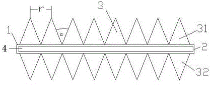
[0012] As shown in the figure, a low-resistance heater includes a main pipe 1 and fins 3. The main pipe 1 is provided with a rectangular through hole 4, and the inner side of the main pipe 1 is provided with a heating part 2. The heating part The distance between 2 and the main pipe 1 is 0.5mm, and the two are closely attached. The fins 3 are arranged outside the main pipe 1 in a zigzag shape, and the fins 3 are arranged perpendicular to the main pipe 1. The fins 3 are arranged vertically to the main pipe 1. The angle between 3 is α, and α is 40°-60°. The fins 3 include upper fins 31 and lower fins 32, and the upper fins 31 and lower fins 32 are arranged oppositely. The distance between the fins 3 is r, and r is 5-8mm.

[0013] A low-resistance heater provided by the present invention has a rectangular through hole in the main pipe. The rectangular through hole has the best circulation effect and does not cause backflow; The distance between the two is 0.5mm, the two are clos...


PUM


Abstract

The invention provides a low-wind-resistance heater. The low-wind-resistance heater comprises a main pipe and fins, wherein a rectangular through hole is formed in the main pipe, so that the circulation effect is optimal and no reflux phenomenon is generated; a heating component is arranged on the inner side of the main pipe, the distance between the heating component and the main pipe is 0.5mm, and the heating component is closely attached to the main pipe, so that the heat transfer effect is better and the conversion rate is higher; the fins are arranged on the outer side of the main pipe in a zigzag manner and are vertical to the main pipe; the included angle alpha between every two fins is 40-60 degrees; the fins include upper fins and lower fins, wherein the upper fins are opposite to the lower fins, and the distance between every two fins is 5-8mm. According to the low-wind-resistance heater, the wind resistance is low, the conversion is high and the purpose of saving energy by reducing the wind speed loss is achieved.

Description

technical field [0001] The invention relates to the field of heaters. Background technique [0002] The heater is a commonly used electric heating device. It is loved by people because of its small size, high heating power, and fast heating. It has a wide range of applications, long life, and high reliability. The core of the principle of the heater is energy conversion, the most common is the conversion of electrical energy into heat energy. Due to its high thermal efficiency and fast heating speed, the heater can realize overall uniform heating or partial heating according to the heating process requirements, and is easy to realize vacuum heating and controlled atmosphere heating, and is widely used in production, scientific research and testing and other fields. However, the existing heaters have relatively large air flow resistance, low conversion efficiency, and cannot achieve the purpose of energy saving. Contents of the invention [0003] The problem to be so...

Claims


Application Information

Patent Timeline
Patent Type & Authority Applications(China)
IPC IPC(8): H05B1/00
Inventor 陈桂军李建明
Owner ZHENJIANG DONGFANG ENERGY SAVING EQUIP
Learn More