A yarn placement and fixing frame in textile industry production

A fixing frame and yarn technology, which is applied in the direction of thin material handling, delivery of filamentous materials, transportation and packaging, etc. It can solve the problem of inability to flexibly adjust the direction of yarn lead-out, affect the efficiency of processing, and the axial runout of yarn drums Large radial shaking and other issues

Active Publication Date: 2020-11-13
海宁巨龙新材料股份有限公司
View PDF11 Cites 0 Cited by
  • Summary
  • Abstract
  • Description
  • Claims
  • Application Information

AI Technical Summary

Problems solved by technology

[0005] The present invention provides a yarn placement fixture in textile industry production, aiming at solving the following problems existing in the prior art: (1) During the process of drawing out the yarn, the axial jumping range of the yarn bobbin is large and the radial shaking is obvious; problems, causing the yarn to swing back and forth, reducing the smoothness of yarn delivery, and affecting the efficiency of subsequent processing; (2) During the process of yarn extraction, the direction of yarn extraction cannot be flexibly adjusted, and cannot adapt to the needs of different types of subsequent processing

Method used


Image

  • A yarn placement and fixing frame in textile industry production
  • A yarn placement and fixing frame in textile industry production
  • A yarn placement and fixing frame in textile industry production

Examples


Embodiment Construction

[0032] The embodiments of the present invention will be described in detail below with reference to the accompanying drawings, but the present invention can be implemented in many different ways defined and covered by the claims.

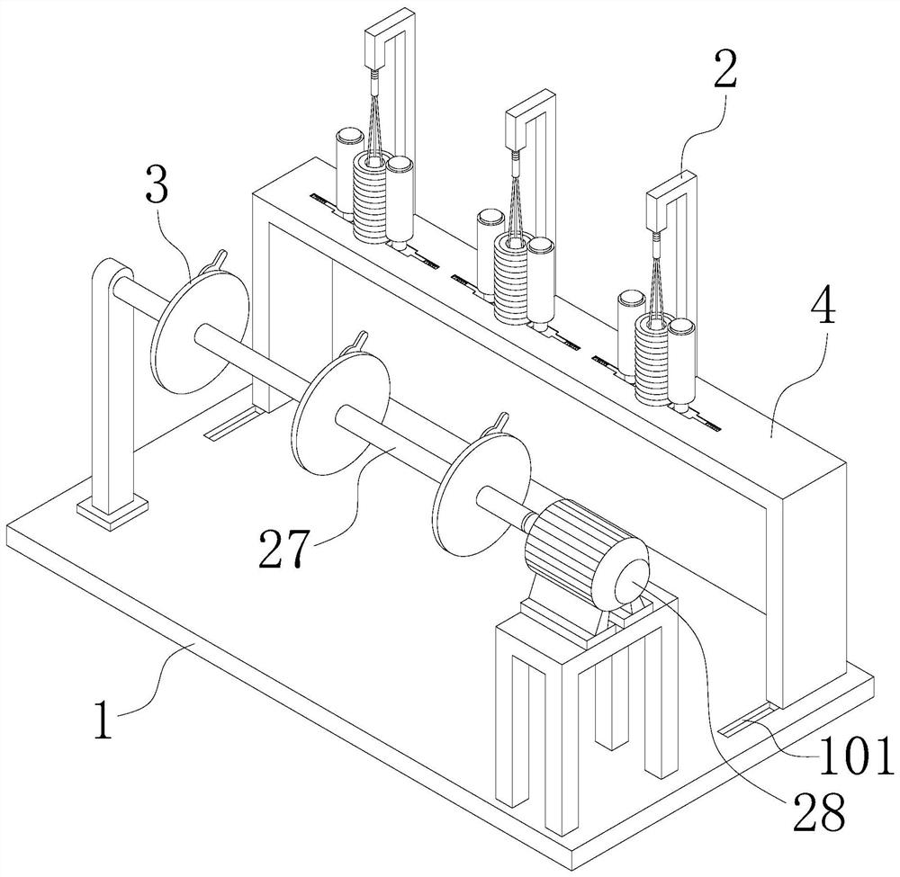
[0033] Such as figure 1 As shown, this embodiment provides a yarn placement fixture in textile industry production, which includes a base 1 on which a fixing mechanism 2 and a direction changing mechanism 3 are arranged.

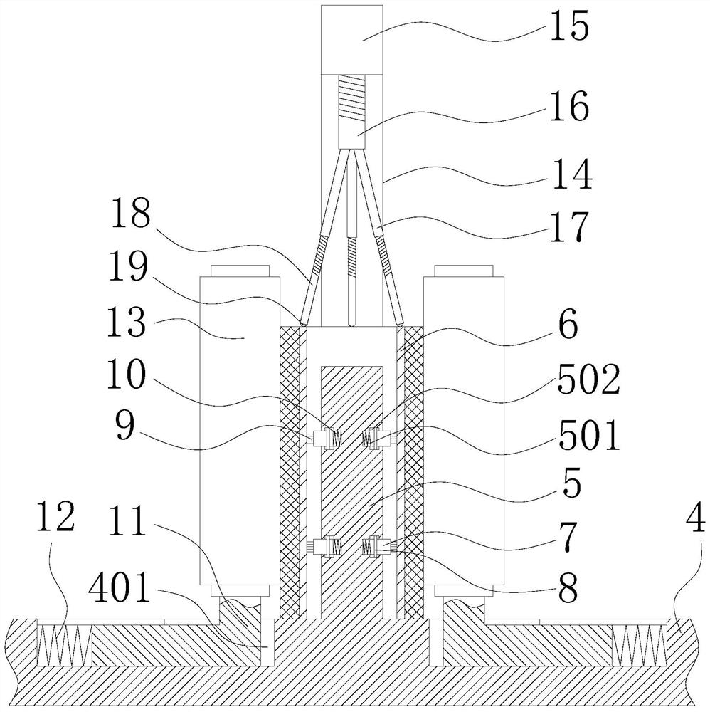
[0034] Such as figure 2 As shown, the fixing mechanism 2 is arranged on the support platform 4 , the fixing mechanism 2 includes a cylindrical support column 5 fixed on the support platform 4 , and the yarn bobbin 6 is sleeved on the support column 5 . The outer surface of the support column 5 is provided with eight first chute 501 along its radial direction, the eight first chute 501 is divided into two layers, the number of each layer is four, and each layer is adjacent to the first chute 501 The included angle along the circ...


PUM


Abstract

The invention belongs to the technical field of textile equipment, and relates to a yarn placing and fixing frame in textile industry production. The yarn placing and fixing frame comprises a base, wherein a fixing mechanism and a side steering mechanism are arranged on the base, the fixing mechanism comprises a cylindrical support column, a sliding block is arranged on the support column, the sliding block is abutted with the inner wall of a yarn barrel through a spring so as to support the interior of the yarn barrel, rollers are arranged on both sides of the yarn barrel, and the rollers areabutted with a yarn outside the yarn barrel under the action of elastic force of the spring so as to externally limit the yarn barrel. According to the yarn placing and fixing frame, the top of the yarn barrel is limited by two groups of threaded rods and threaded sleeves so as to prevent axial runout. The axial and radial degree of freedom of the yarn barrel is limited, so that the yarn is prevented from swinging back and forth in a leading process, and the subsequent processing efficiency is improved. A guide wheel of the side steering mechanism of the yarn placing and fixing frame is hinged to the ends of connecting rods, and the direction of the yarn is controlled by the matching of a plurality of groups of connecting rods, so that the purpose of flexibly adjusting the yarn leading direction is realized.

Description

technical field [0001] The invention belongs to the technical field of textile equipment, and in particular relates to a fixing frame for placing yarns in textile industry production. Background technique [0002] In the production of the textile industry, the yarn is usually wound on the yarn bobbin, and the yarn needs to be drawn out from the yarn bobbin during processes such as weaving and dyeing. Because the yarn drum will be driven to move when the yarn is drawn out, which will affect the efficiency of yarn extraction, so the yarn drum needs to be fixed. The Chinese invention patent with the application number CN201810981205.0 discloses a yarn barrel fixing frame for a loom, including a load-bearing base, a support rod is welded in the middle of the upper end of the load-bearing base, and a square connecting block is installed on the square side of the support rod. The left and right ends of the block are welded with fixed baffles, and the middle position of the outer ...

Claims


Application Information

Patent Timeline
Patent Type & Authority Patents(China)
IPC IPC(8): B65H49/20B65H49/30B65H57/14
CPCB65H49/20B65H49/30B65H57/14B65H2701/31
Inventor 杜秀兰李玮
Owner 海宁巨龙新材料股份有限公司
Why Eureka
Try Eureka