Retractable assistance crank mechanism for bicycle
A power-assisted crank and telescopic technology, which is applied in the crank structure, vehicle parts, transportation and packaging, etc., can solve the problems of variable speed bicycles that do not achieve riding effort, crank distance extension, etc.
- Summary
- Abstract
- Description
- Claims
- Application Information
AI Technical Summary
Problems solved by technology
Method used
Image

Examples
Embodiment
[0032] In order to understand the above-mentioned purpose, features and advantages of the present application more clearly, the present invention will be further described in detail below in conjunction with the accompanying drawings and specific embodiments. It should be noted that, in the case of no conflict, the embodiments of the present application and the features in the embodiments can be combined with each other.
[0033] In the following description, many specific details are set forth in order to fully understand the application, but the application can also be implemented in other ways different from those described here, therefore, the protection scope of the application is not limited by the specific details disclosed below. EXAMPLE LIMITATIONS.
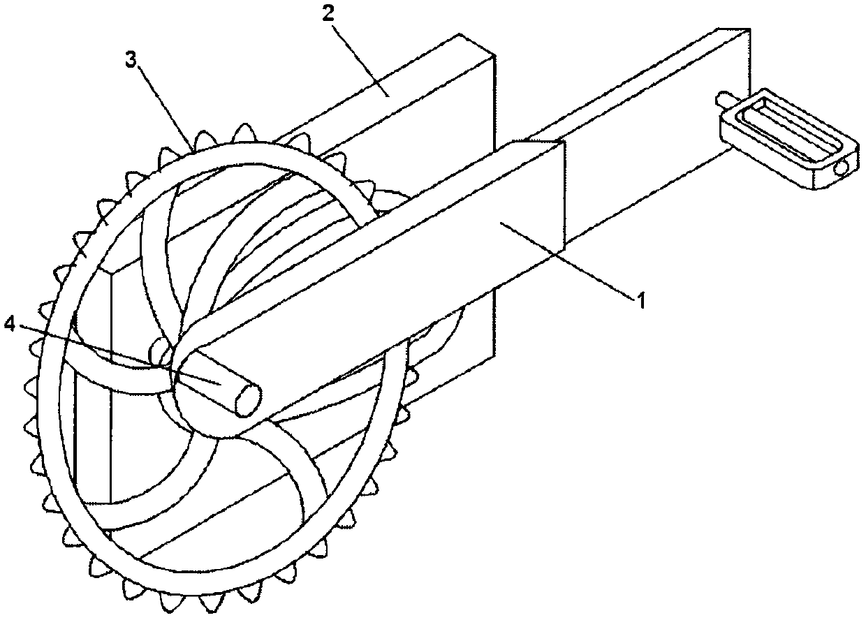
[0034] The invention proposes a telescopic power-assisted crank mechanism for bicycles, which includes a telescopic crank 1, a track mechanism 2, a large toothed disc 3 and a main shaft 4.
Embodiment 1
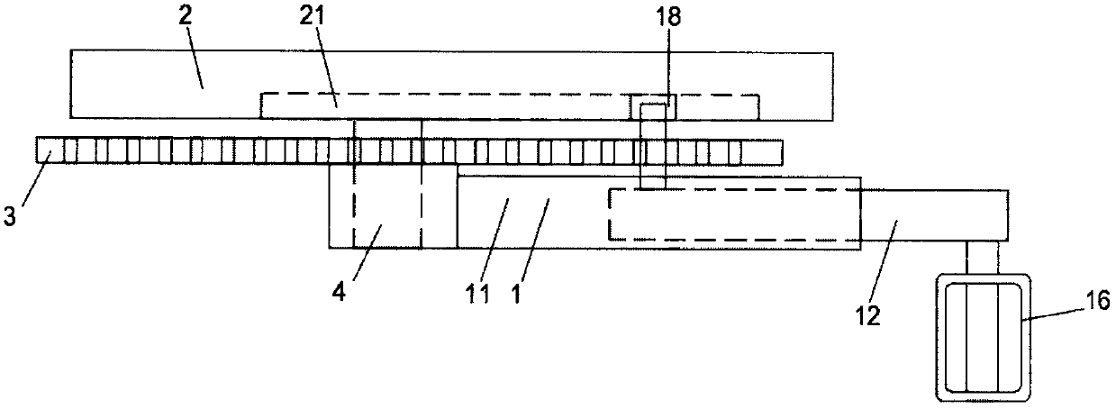
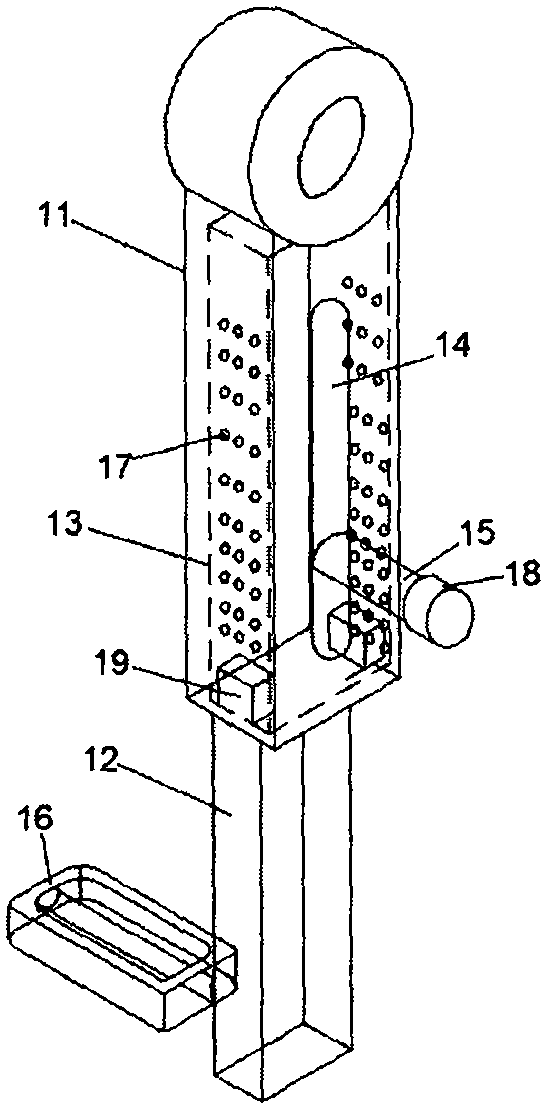
[0036] Such as Figure 1 to Figure 4 It shows a structural schematic diagram, a side view, a structural diagram of the telescopic crank, and a track diagram of the telescopic crank of the present invention.
[0037] The telescopic power-assisted crank mechanism for bicycles includes a telescopic crank 1, a track mechanism 2 and a large toothed disc 3, the telescopic crank 1, the track mechanism 2 and the large toothed disc 3 are connected by a main shaft 4, and the main shaft 4 is fixed on the track mechanism 2, and the track mechanism 2 is fixed on the bicycle, the telescopic crank 1 and the large toothed plate 3 can rotate along the main shaft 4, the large toothed plate 3 is between the telescopic crank 1 and the track mechanism 2, the large toothed plate 3 is fixed on the telescopic crank 1, and the large toothed plate 3. Rotate along with the rotation of the telescopic crank 1, the chain can be suspended on the large toothed disc 3, and the telescopic crank 1 rotates to dr...
Embodiment 2
[0044] Such as Figure 1 to Figure 4 It shows a structural schematic diagram, a side view, a structural diagram of the telescopic crank, and a track diagram of the telescopic crank of the present invention.
[0045] The telescopic power-assisted crank mechanism for bicycles includes a telescopic crank 1, a track mechanism 2 and a large toothed disc 3, the telescopic crank 1, the track mechanism 2 and the large toothed disc 3 are connected by a main shaft 4, and the main shaft 4 is fixed on the track mechanism 2, and the track mechanism 2 is fixed on the bicycle again. The telescopic crank 1 and the large toothed disc 3 can rotate along the main shaft 4. The large toothed disc 3 is between the telescopic crank 1 and the track mechanism 2. The large toothed disc 3 is fixed on the telescopic crank 1. The large toothed disc 3 is fixed on the telescopic crank 1. Disc 3 rotates along with the rotation of telescopic crank 1, and chain can be suspended on the large toothed disc 3, and...
PUM
 Abstract
Description
Claims
Application Information
 - R&D
- Intellectual Property
- Life Sciences
- Materials
- Tech Scout
- Unparalleled Data Quality
- Higher Quality Content
- 60% Fewer Hallucinations
Browse by: Latest US Patents, China's latest patents, Technical Efficacy Thesaurus, Application Domain, Technology Topic, Popular Technical Reports.
© 2025 PatSnap. All rights reserved.Legal|Privacy policy|Modern Slavery Act Transparency Statement|Sitemap|About US| Contact US: help@patsnap.com