
System and method for thermoforming object

一种热成形、物体的技术,应用在增材制造领域

Inactive Publication Date: 2019-11-01
GENERAL ELECTRIC CO
View PDF1 Cites 1 Cited by
  • Summary
  • Abstract
  • Description
  • Claims
  • Application Information

AI Technical Summary

Problems solved by technology

The pressure tank is operable to create a pressure differential across the surface

Method used


Image

  • System and method for thermoforming object
  • System and method for thermoforming object
  • System and method for thermoforming object

Examples


Embodiment Construction

[0020] Reference will now be made in detail to exemplary embodiments of the present invention, examples of which are illustrated in the accompanying drawings. Wherever possible, the same reference characters used in all the drawings refer to the same or like parts, and description will not be repeated.

[0021] As used herein, the terms "substantially", "substantially" and "about" indicate conditions within reasonably achievable manufacturing and assembly tolerances relative to ideal desired conditions suitable for achieving the functional purpose of the component or assembly. As used herein, "electrically coupled," "electrically connected," and "electrically communicating" means connecting the referenced elements, directly or indirectly, such that electrical current can flow from one element to the other. The connection may comprise a direct conductive connection, ie without intervening capacitive, inductive or active components, an inductive connection, a capacitive connecti...


PUM

PropertyMeasurementUnit
diameteraaaaaaaaaa

Abstract

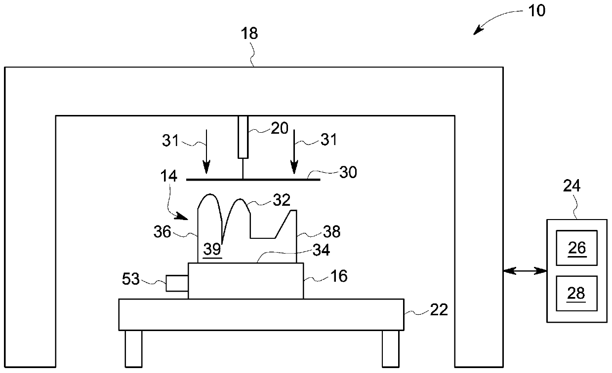
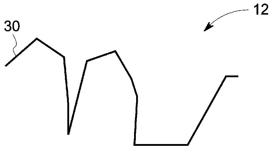
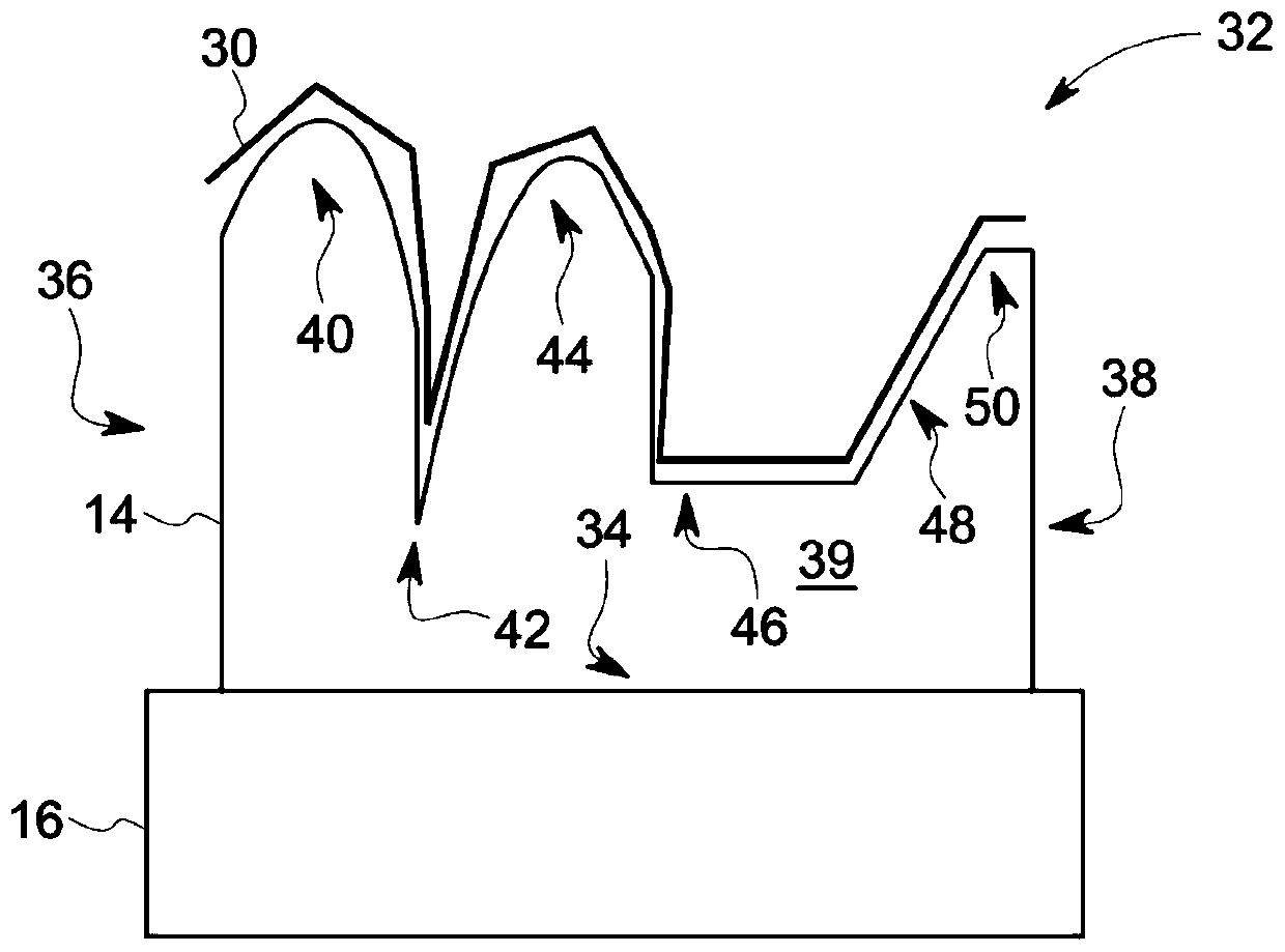
The invention provides a system and a method for thermoforming object. A system 10 for thermoforming an object 12 is provided. The system 10 includes a mold 14 and a pressure-box 16. The mold 14 has asurface 32 that defines a shape of the object 12 and includes two or more portions 40, 42, 44, 46, 48, 50 of differing porosities. The pressure-box 16 is operative to generate a pressure differentialacross the surface 32. The two or more portions 40, 42, 44, 46, 48, 50 apply the pressure differential at different loads, based at least in part on the differing porosities, to a material 30 disposed onto the surface 32 so as to form the object 12 by deforming the material 30 into the shape.

Description

technical field [0001] Embodiments of the present invention relate generally to additive manufacturing, and more particularly, to systems and methods for thermoforming objects. Background technique [0002] Thermoforming is a manufacturing process in which a plastic sheet, also called a "film", is heated to a pliable forming temperature, formed into a specific shape in a mold and then trimmed to form a usable product. Many thermoforming processes use a die that has at least one surface with a plurality of holes that allow a vacuum to pull, or "suck," the film against the surface in order to stretch and / or otherwise deform the film to It conforms to the shape of the surface. [0003] The holes for such molds are usually drilled through the surface after the body of the mold has been formed. However, as will be appreciated, due to technical and / or structural constraints, it is often impractical and difficult to drill holes at certain locations along the surface, such as at s...

Claims


Application Information

Patent Timeline
Patent Type & Authority Applications(China)
IPC IPC(8): B29C64/147B29C64/20B33Y10/00B33Y30/00
CPCB29C64/147B29C64/20B33Y10/00B33Y30/00B29C51/10B29C51/365B29K2855/02B29K2869/00B29K2079/00B29C2791/006B29C2791/007B29C51/36B29C33/3814B29C51/18B29K2105/256B29K2879/085B29K2905/00
Inventor 爱德华·约翰·卡斯蒂略杰西·爱德华·施林普夫
Owner GENERAL ELECTRIC CO
Learn More