Cordierite ceramic body and method

a ceramic body and cordierite technology, applied in the field of cordierite bodies, can solve the problems of high pressure drop, high strength, and very low pressure drop of carbon soot, and achieve the effects of low strength, high filtration efficiency and low pressure drop

Inactive Publication Date: 2005-03-08
CORNING INC
View PDF16 Cites 155 Cited by
  • Summary
  • Abstract
  • Description
  • Claims
  • Application Information

AI Technical Summary

Benefits of technology

[0009]The inventive ceramic bodies are suitable in high temperature applications, and particularly as diesel exhaust filtration devices exhibiting low pressure drops, high filtration efficiency and good strength. In a preferred embodiment there is provided a DPF comprising a honeycomb body, and having an inlet end and an outlet end, a multiplicity of cells extending from the inlet end to the outlet end, the cells having porous walls, wherein part of the total number of cells at the inlet end are plugged along a portion of their lengths, and the remaining part of the cells that are open at the inlet end are plugged at the outlet end along a portion of their lengths, so that an engine exhaust stream passing through the cells of the honeycomb from the inlet end to the outlet end flows into the open cells, then through the cells walls, and out of the structure through the open cells at the outlet end.

Problems solved by technology

However, the combination of high filtration efficiency, high strength, and very low pressure drop has proven elusive with cordierite DPFs.
While such DPFs have adequate filtration efficiency and strength, their pressure drop when loaded with carbon soot is high.
However, strengths for filters with such high porosity and coarse pore size are so low that especially careful handling is required.
Furthermore, these filters still exhibit an undesirably high rate of increase in pressure drop with the addition of the first gram / liter of soot, although not as severe as for previously available lower-porosity filters with finer pore size.
Work by the present investigator has shown that further reduction in pressure drop is possible when median pore size is increased beyond 25 μm; however, such cordierite ceramic bodies have a low filtration efficiency.

Method used


Image

  • Cordierite ceramic body and method
  • Cordierite ceramic body and method
  • Cordierite ceramic body and method

Examples


examples

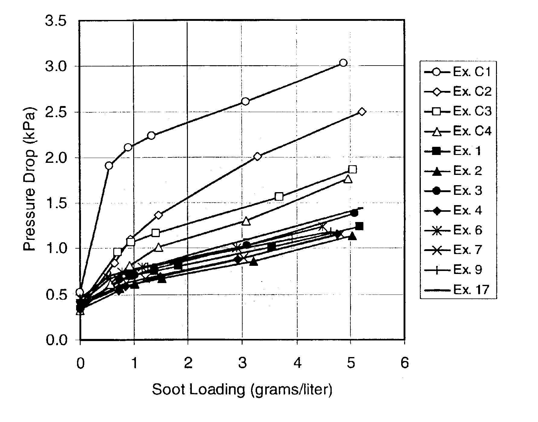
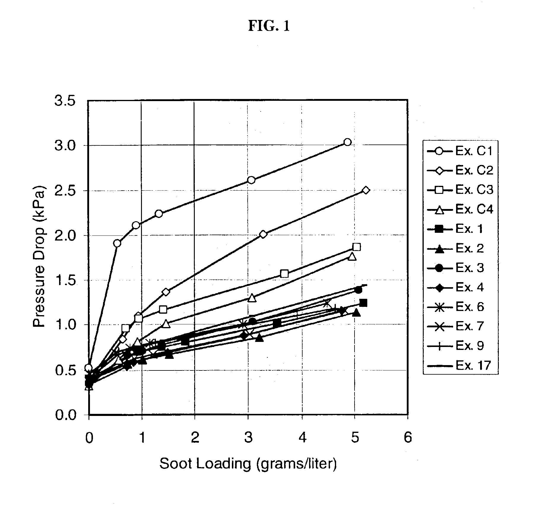
[0038]Inventive and comparative examples were prepared by mixing together selected raw materials from Table 1 in the proportions listed for the examples in Tables 2, 3, 4 and 5. 100 parts by weight of the dry ingredients (oxides plus pore formers) were mixed with about 4 to 6 parts by weight methyl cellulose and 1 part by weight sodium stearate. The contents were then plasticized with about 25 to 40 parts by weight deionized water and extruded into honeycomb having a nominal cell density of 200 cells / inch2 and a wall thickness of 0.012 inches. The honeycombs were dried and subsequently fired to a temperature of 1405 to 1415° C., held at that temperature for 11 or 25 hours, respectively, and then cooled to room temperature.

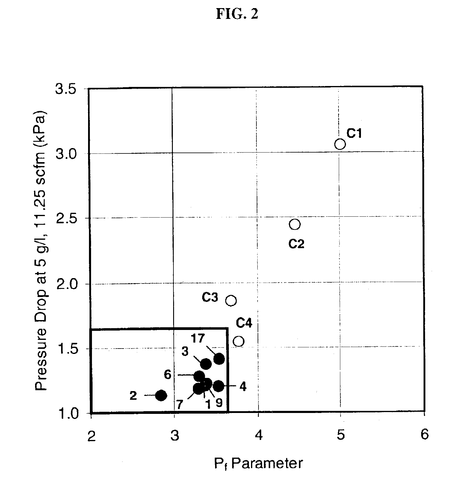
[0039]Comparative (non-inventive) examples and properties measured thereon are provided in Table 2. Inventive examples and respective properties are provided in Tables 3 to 5. Pore volume, % porosity, and pore size distribution were measured by mercury porosimetry....


PUM

PropertyMeasurementUnit
specific surface areaaaaaaaaaaa
median particle diameteraaaaaaaaaa
porosityaaaaaaaaaa

Abstract

A cordierite ceramic body having (i) a pore size distribution and a porosity which satisfy the relationship 10.2474 / [(d50)2(pore fraction)]+0.0366183(d90)−0.00040119(d90)2+0.468815(1 / pore fraction)2+0.0297715(d50)+1.61639(d50−d10) / d50≦3.65, and (ii) a CTE (25°-800° C.) of ≦15×10−7 / ° C., wherein the cordierite ceramic body is produced from a moldable mixture comprising cordierite-forming raw materials including (a) a fine talc having a median particle diameter, as measured by laser diffraction, of less than 10 micrometers, and a B.E.T. specific surface area of greater than 5 m2 / g, and (b) a pore former. The cordierite ceramic body is suitable in the fabrication of cellular, wall-flow diesel particulate filters having a low pressure drop, high filtration efficiency and improved strength.

Description

BACKGROUND OF INVENTION[0002]The present invention relates to cordierite bodies, and especially the kind with properties suitable for use in exhaust after-treatment applications, particularly diesel exhaust filtration.[0003]Cordierite ceramic bodies, especially such formed as honeycomb multicellular structures, find employment in a number of high temperature applications such as catalytic converters, NOx adsorbers, electrically heated catalysts, molten metal filters, regenerator cores, chemical process substrates, catalysts for hydrodesulfurization, hydrocracking, or hydrotreating, and filters such as diesel particular filters.[0004]In diesel exhaust filtration, cordierite, being a low-cost material, in combination with offering a low coefficient of thermal expansion (CTE), has been the material of choice. Porous cordierite ceramic filters of the wall-flow type have been utilized for the removal of particles in the exhaust stream from some diesel engines since the early 1980s. A die...

Claims


Application Information

Patent Timeline
Patent Type & Authority Patents(United States)
IPC IPC(8): B01D46/24C04B35/195C04B35/636C04B38/00
CPCB01D46/2429C04B35/195C04B35/632C04B35/6365C04B38/0006C04B38/0054C04B38/0067C04B38/068C04B38/067B01D46/2444C04B2235/9607C04B2235/96C04B2235/77C04B2235/6021C04B2235/5445C04B2235/5436C04B2235/5409C04B2235/449C04B2235/349B01D46/247B01D2046/2433B01D2046/2437B01D2046/2496B01D2275/30C04B2111/00793C04B2235/3217C04B2235/3218C04B2235/3418C04B2235/3445B01D46/24492B01D46/24491B01D46/2498B01D46/24494
Inventor MERKEL, GREGORY A.
Owner CORNING INC
Why Eureka
Try Eureka