Gas separation devices

a gas separation device and physiological fluid technology, applied in separation processes, liquid degasification, filtration separation, etc., can solve the problems of dangerous gas particles, devices mentioned are not both efficient mixing blood and any infusion or replacement fluid, and can not effectively degass both fluids, etc., to achieve effective operation

Active Publication Date: 2009-04-14
GAMBRO LUNDIA AB
View PDF154 Cites 86 Cited by
  • Summary
  • Abstract
  • Description
  • Claims
  • Application Information

AI Technical Summary

Benefits of technology

[0027]The object of the present invention is to provide a gas separation device for a physiological fluid, for example blood, which is capable of operating effectively even at high flow rates, while minimizing the total volume of blood that is to be held within the said device.
[0028]A further object of the invention is to provide an optimal quality of the flow through the gas separation device, by essentially eliminating the presence of stagnation points and reducing pressure drops to a minimum.
[0030]Another object of the invention is to provide a gas separation device capable of offering an optimal area for access by at least one infusion line, thus permitting an efficient mixing of the blood with the infusion fluid while carrying out effective and simultaneous separation of any gas from the infusion fluid and from the blood, and while minimizing the air-blood interface.
[0031]A further object of the present invention is to provide a fluid mixing device with gas separation, capable of operating effectively even at high flow rates, while minimizing the air-blood interface.
[0032]The invention also has the object of reducing to the smallest possible level the total volume of blood occupying the said device.

Problems solved by technology

It should be pointed out that this is because excessively large gas particles can be dangerous if they are transferred to a patient's cardiovascular system.
In the second place, the devices mentioned are not capable of both efficiently mixing the blood with any infusion or replacement fluid that may be present and simultaneously and effectively degassing both fluids.
It should also be noted that the conventional solutions require the presence of a relatively high volume within the gas separation device; in the case of dialysis treatment, for example, the quantity of blood constantly occupying the interior of the separation device increases to a considerable and undesired extent the total amount of blood kept outside the patient.
The presence of the filter not only increases the overall cost of the device, but also constitutes an additional element which may lead to encrustation and undesired deposits of particles, particularly when part of the filter is located in an air-blood interface area.
Moreover, the known devices which have been described are relatively unsuitable for permitting high blood flows (of the order of 500 ml / min.

Method used


Image

  • Gas separation devices
  • Gas separation devices
  • Gas separation devices

Examples


Embodiment Construction

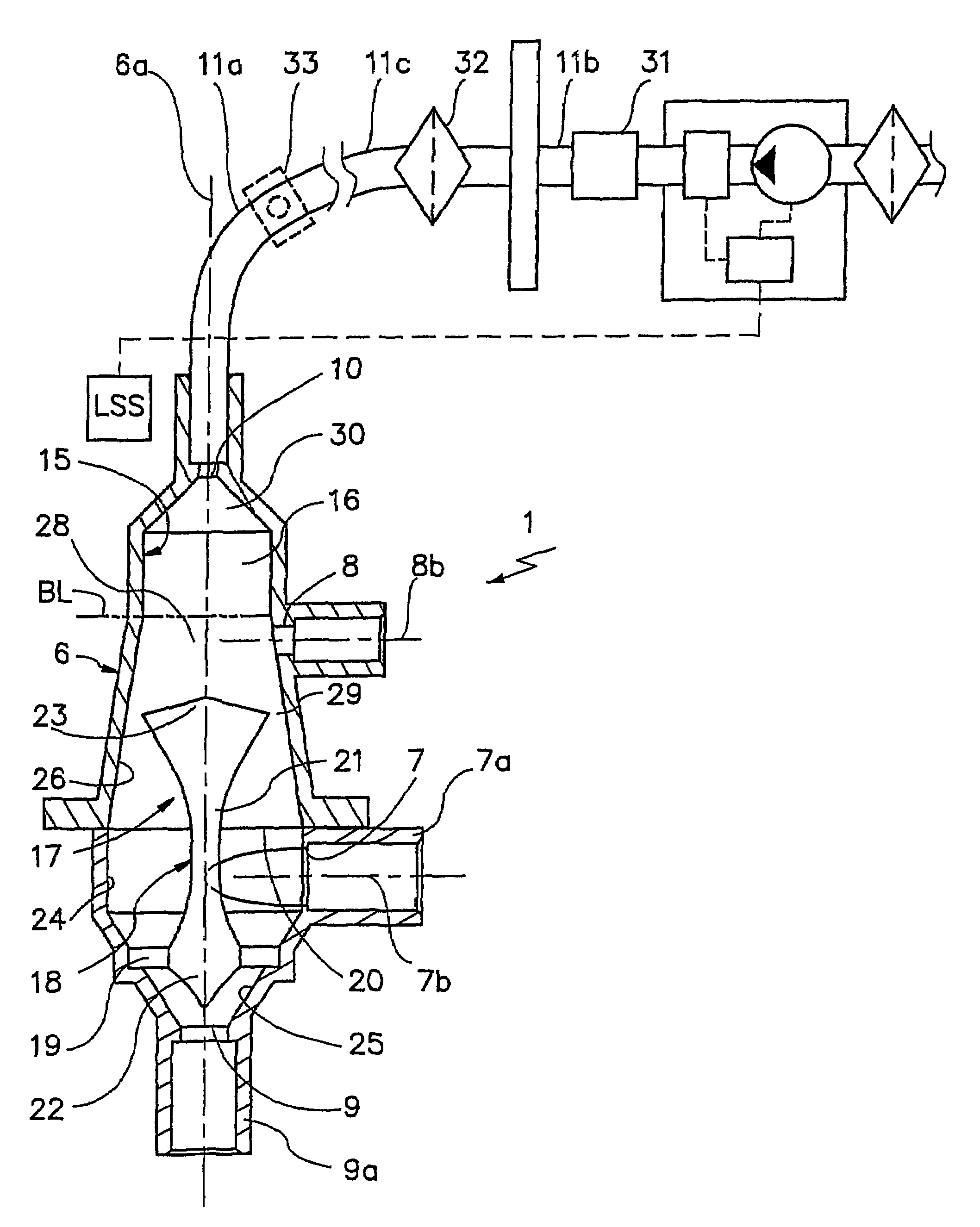
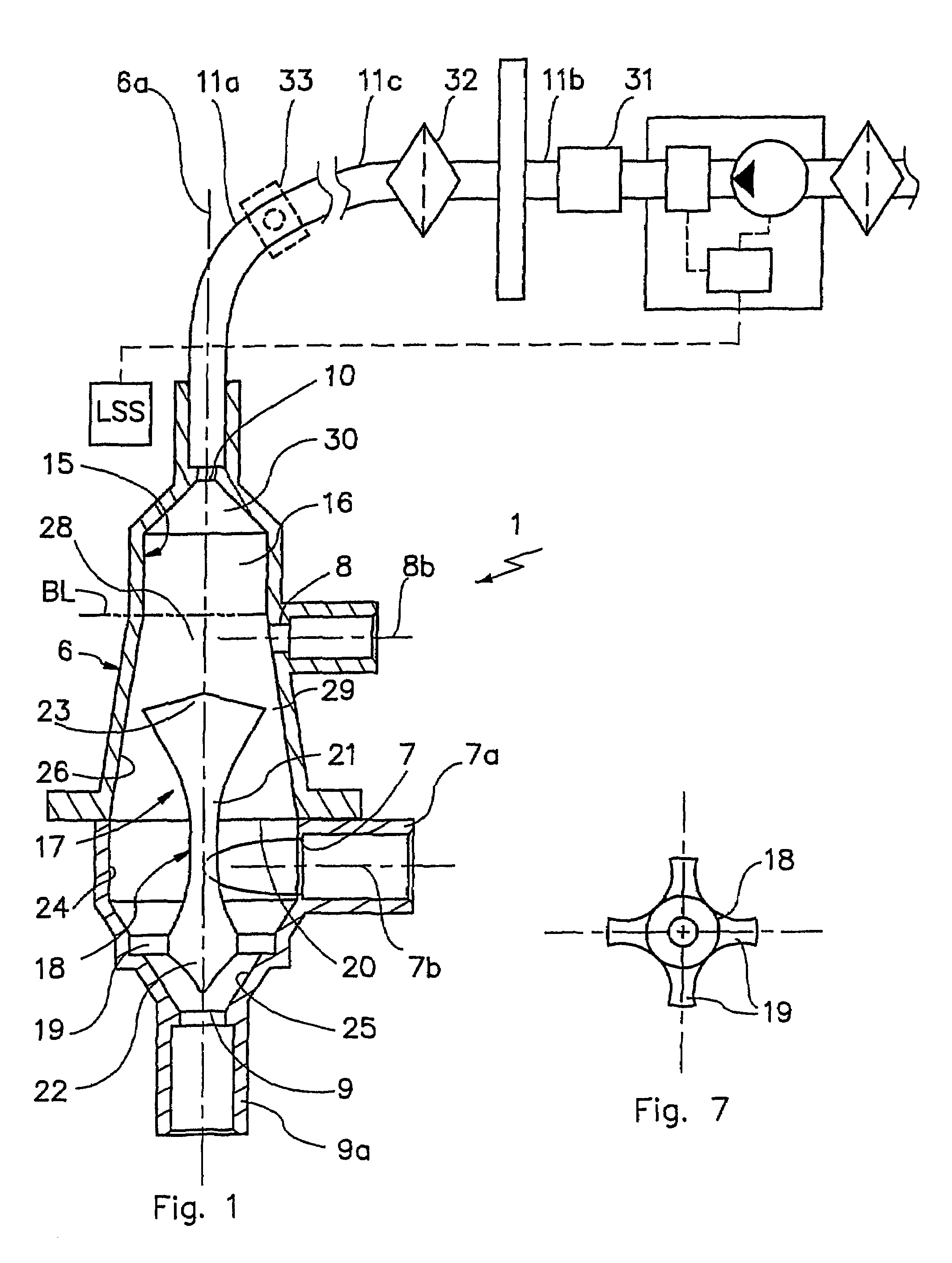
[0044]With reference to FIG. 1, the number 1 indicates a fluid mixing device with gas separation.

[0045]As shown in FIG. 6, the device 1 can operate in a disposable line 2 for extracorporeal blood treatment, comprising a branch 3 for withdrawing the blood from the patient, a blood treatment unit 4 and a branch 5 for returning the blood to the patient.

[0046]In greater detail, the unit 4, a dialysis filter for example, is interposed between the two branches 3 and 5, while the device 1 operates on the return branch 5, up-line from the point of access to the patient's vascular system.

[0047]The device 1 comprises a containing body 6, having a longitudinal axis of symmetry 6a; the body 6 forms an internal volume 16 which is designed to receive a specified quantity of fluid and which has a radial dimension significantly larger than that of the branches 3 and 5, so that the velocity of the said fluid is decreased and the gas is efficiently separated, as described below.

[0048]In operating con...


PUM

PropertyMeasurementUnit
thicknessaaaaaaaaaa
diameteraaaaaaaaaa
thicknessaaaaaaaaaa

Abstract

A description is given of a gas separation device for a physiological fluid, comprising a containing body (6) having at least a first inlet aperture (7) for a physiological fluid, positioned with a tangential direction of access, at least one outlet aperture (9) for the said fluid, spaced apart from the said inlet aperture, and a guide element (17) housed within the said body. The guide element (17) has a continuous active surface (15) designed to contact and guide the said fluid and delimits, together with the containing body (6), a first annular chamber (20) into which the first inlet aperture (7) opens directly.

Description

BACKGROUND OF THE INVENTION[0001]The present invention relates to a gas separation device for physiological fluids, particularly for cellular fluids such as blood. The present invention relates also to a fluid mixing device with gas separation.[0002]It is known that any gas particles present in a physiological fluid, such as blood circulating in an extracorporeal circuit, must be effectively removed when the fluid is to be administered to a patient. It should be pointed out that this is because excessively large gas particles can be dangerous if they are transferred to a patient's cardiovascular system.[0003]It is also known that some treatments require the simultaneous administration to a patient of both a physiological fluid, for example blood circulating in an extracorporeal circuit, and an additional fluid, for example an infusion or replacement liquid. However, before the two fluids, for example blood and infusion liquid, are transferred to the patient, it is necessary to remov...

Claims


Application Information

Patent Timeline
Patent Type & Authority Patents(United States)
IPC IPC(8): B01D19/00A61M1/34A61M1/36B01F5/00B04C5/103
CPCA61M1/3627A61M1/3676B01F5/0057B04C5/103A61M1/3437A61M1/3641B01D19/0057A61M1/3639A61M2205/3382A61M2206/16B01F25/10B01D19/00
Inventor CHEVALLET, JACQUESSEMENZATO, NICOLASFRUGIER, ALAINRIBOLZI, FRANCESCO
Owner GAMBRO LUNDIA AB
Why Eureka
Try Eureka