Co-current vapor-liquid contacting apparatus

a vapor liquid and contacting apparatus technology, applied in the direction of liquid degasification, combustion air/fuel air treatment, separation processes, etc., can solve the problems of increasing pressure drop, reducing the fluid may not be readily redistributed along the length of the apparatus, so as to increase the capacity and efficiency of the apparatus, reduce the pressure drop, and reduce the effect of redistribution

Active Publication Date: 2008-09-16
UOP LLC
View PDF17 Cites 86 Cited by
  • Summary
  • Abstract
  • Description
  • Claims
  • Application Information

AI Technical Summary

Benefits of technology

[0015]An advantage of the present invention is that the non-parallel orientation of one contacting stage with respect to a vertically adjacent stage adds a degree of freedom for distributing the vapor and liquid in multiple directions. If a maldistribution of liquid or vapor occurs, the fluid is readily redistributed. Thus, a maldistribution of liquid or vapor is eliminated in as few as one or two stages, thereby increasing the capacity and efficiency of the apparatus over the conventional art. The present invention also provides for relatively unobstructed passage of the vapor ascending from an inferior stage to a superior contacting volume which has the advantage of a lower pressure drop compared to previous apparatus.
is that the non-parallel orientation of one contacting stage with respect to a vertically adjacent stage adds a degree of freedom for distributing the vapor and liquid in multiple directions. If a maldistribution of liquid or vapor occurs, the fluid is readily redistributed. Thus, a maldistribution of liquid or vapor is eliminated in as few as one or two stages, thereby increasing the capacity and efficiency of the apparatus over the conventional art. The present invention also provides for relatively unobstructed passage of the vapor ascending from an inferior stage to a superior contacting volume which has the advantage of a lower pressure drop compared to previous apparatus.

Problems solved by technology

If maldistribution of liquid or vapor occurs in a vapor-liquid contacting apparatus having a parallel arrangement on adjacent stages, it is known that the fluid may not be readily redistributed along the length of the apparatus.
Thus, maldistribution of liquid or vapor may propagate from one stage to the next, reducing the capacity and efficiency of the apparatus.
In addition, the use of perforated decks in a relatively small area within the column may greatly increase pressure drop, even if the fractional open area is high.
Therefore, what is needed is an improved co-current vapor-liquid contacting device with non-parallel stages and structures for transferring liquid from one stage to the next inferior stage without reducing liquid handling capability.

Method used


Image

  • Co-current vapor-liquid contacting apparatus
  • Co-current vapor-liquid contacting apparatus
  • Co-current vapor-liquid contacting apparatus

Examples


Embodiment Construction

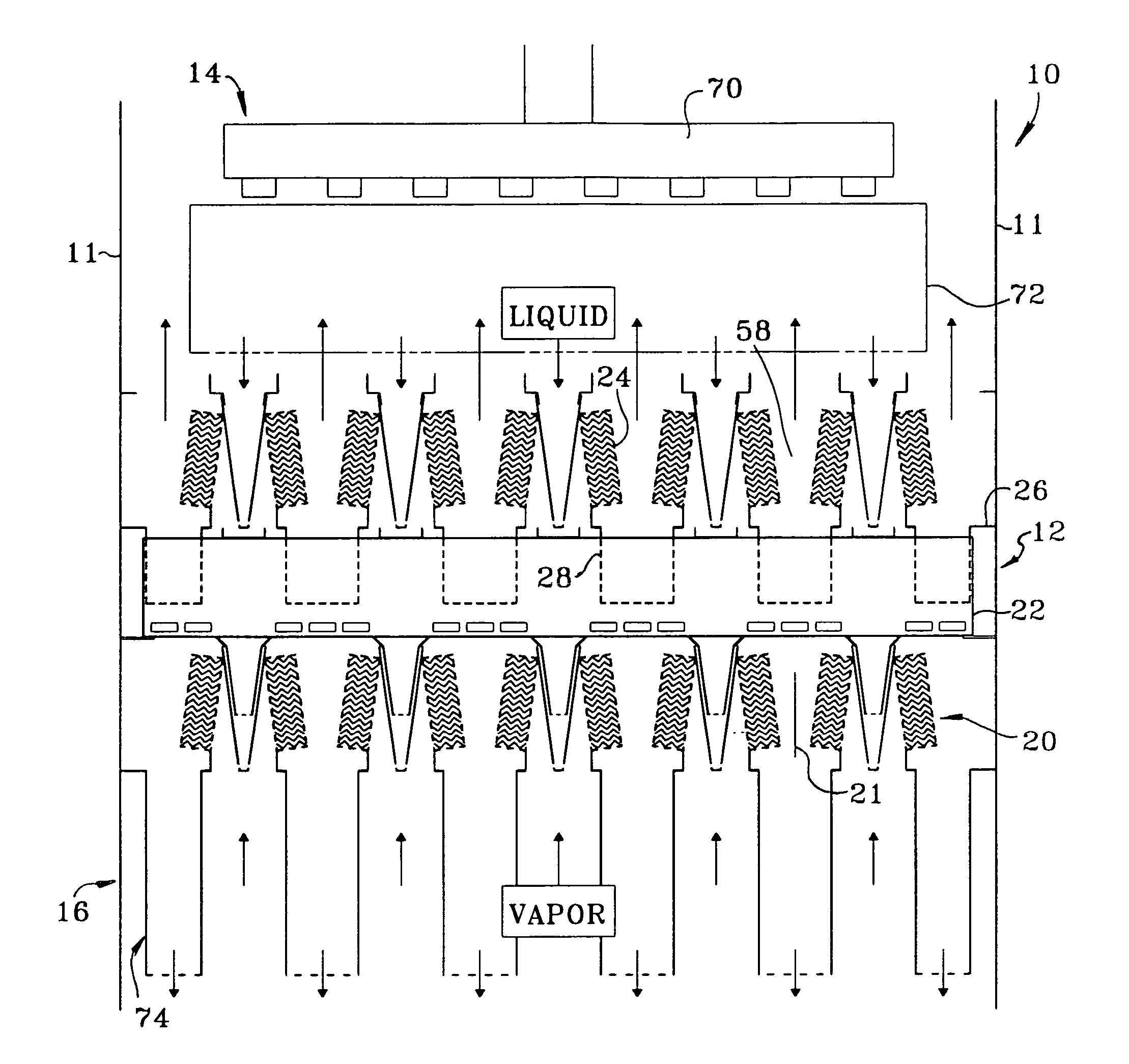
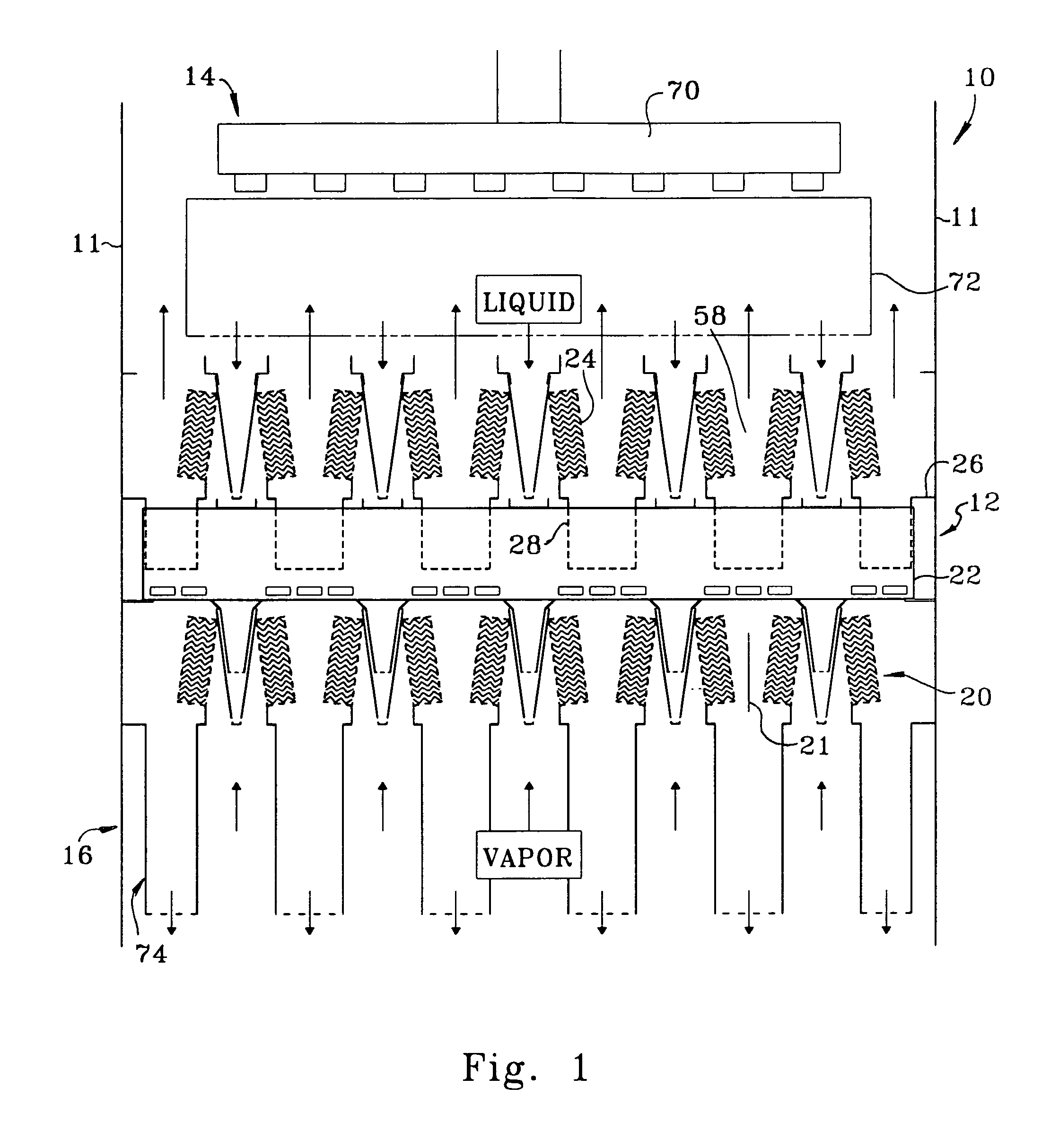
[0029]Referring to FIG. 1, there is shown an embodiment of the co-current vapor-liquid contacting apparatus of the present invention within a vessel 10. The vessel 10 may be for example a distillation column, absorber, direct contact heat exchanger, or other vessel used to conduct vapor-liquid contacting. The vessel 10 contains contacting stages 12 according to the subject invention and two optional collector / distributors. An upper portion of the column contains top collector / distributor 14 and a lower portion of the column contains bottom collector / distributor 16. For simplicity, only three contacting stages are shown. As is well known in the art, a distillation column may contain several sections. Each section may contain numerous contacting stages, and there may be a plurality of fluid feeds and / or withdraws between and / or within sections. Also, different contacting devices such as co-current contacting devices and other conventional distillation devices may be mixed in the same ...


PUM

PropertyMeasurementUnit
rotationaaaaaaaaaa
rotationaaaaaaaaaa
angleaaaaaaaaaa

Abstract

The invention is a high capacity and high efficiency co-current vapor-liquid contacting apparatus for use in distillation columns and other vapor-liquid contacting processes. The apparatus is characterized by an arrangement of modules in horizontal stages rather than tray-like construction. The modules define a co-current contacting volume and in an exemplary configuration the modules include a liquid distributor, a demister, a receiving pan and a duct. The modules of one stage are rotated to be non-parallel with respect to the modules of an inferior stage, a superior stage, or both. Variations relate to the design of the individual elements such as the demister, liquid distributor, ducts, and contacting volumes, and the overall arrangement of the apparatus.

Description

CROSS REFERENCE TO RELATED APPLICATION[0001]This application claims priority from Provisional Application No. 60 / 751,041 filed Dec. 16, 2005, the contents of which are hereby incorporated by reference in their entirety.FIELD OF THE INVENTION[0002]The invention relates to an apparatus useful for performing fractional distillation or other forms of vapor-liquid contacting for mass and / or heat transfer. The invention more specifically relates to a process and apparatus providing a high capacity and high efficiency co-current flow fractionation apparatus useful in fractional distillation columns to separate volatile chemicals such as hydrocarbons.BACKGROUND OF THE INVENTION[0003]Vapor-liquid contacting devices, such as fractionation trays and packings, are employed to perform an almost endless variety of separations in the petroleum and petrochemical industries. For the purposes of this application, the terms “vapor” and “gas” are used interchangeably. Fractionation trays are used, for ...

Claims


Application Information

Patent Timeline
Patent Type & Authority Patents(United States)
IPC IPC(8): B01F3/04
CPCB01D1/305B01D3/28B01D3/324B01J19/32B01J2219/32408B01J2219/32213B01J2219/32234B01J2219/32241B01J2219/32251B01J2219/3221B01J10/00B01J14/00B01F23/20
Inventor XU, ZHANPINGNOWAK, BRIAN J.HELDWEIN, THOMAS C.AGNELLO, JOSEPHCRISCIONE, ANDREW J.MUCK, AARON J.
Owner UOP LLC
Why Eureka
Try Eureka