Safety Stirrup

a safety stirrup and stirrup technology, applied in the field of horse riding stirrup, can solve the problems of many people being injured or killed, not having enough time to withdraw their foot from the stirrup, and serious injury or death, and achieve the effects of convenient use, reduced manufacturing cost, and simple structur

Inactive Publication Date: 2007-07-12
BOSTOCK DEV
View PDF14 Cites 2 Cited by
  • Summary
  • Abstract
  • Description
  • Claims
  • Application Information

AI Technical Summary

Benefits of technology

[0018] It is an object of the present invention to provide a two-way safety stirrup that provides the desirable advantages of release in the event of the rider being dismounted, but which is less prone to unexpected release when pressure is applied in the forward direction. It is a further object to pro...

Problems solved by technology

One of the problems associated with stirrups of the prior art is that if the rider is dismounted or thrown, they may not have sufficient time to withdraw their foot from the stirrup.
If the foot remains trapped in the stirrup, and the horse continues moving, the rider can be dragged along, often causing serious injury or death.
Each year many people are injured or killed in this type of accident.
However this type of safety stirrup suffers from the drawback that it may break away from the stirrup strap during particularly hard riding, leaving the rider unbalanced, and unable to control the horse using his or her feet.
Furthermore, the rider cannot re-mount until a new stirrup is fitted, which can be difficult or inconvenient if the stirrup breaks away in an isolated area.
Furthermore, the frangible stirrup does not prevent leg injuries and is therefore of limited value for novice or disabled riders.
A further disadvantage is that these stirrups are very bulky in the region where they attach to the stirrup strap and the increased bulk often causes excessive wear to the rider's clothing.
However they are not specifically designed to release if the rider's foot moves upwards as he or she is dismounted, a common occurrence, particularly if the horse is bucking or jumping.
Because the stirrup only opens up in one way or one direction, it is important that the rider's foot is inserted from the correct side of the stirrup, otherwise the release mechanism will not operate properly.
While the one-way stirrup...

Method used


Image

  • Safety Stirrup
  • Safety Stirrup
  • Safety Stirrup

Examples


Embodiment Construction

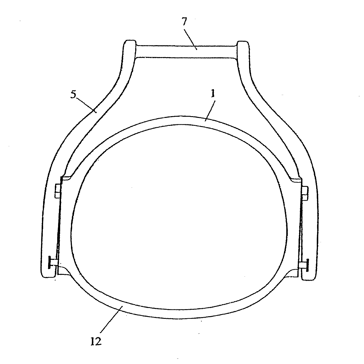
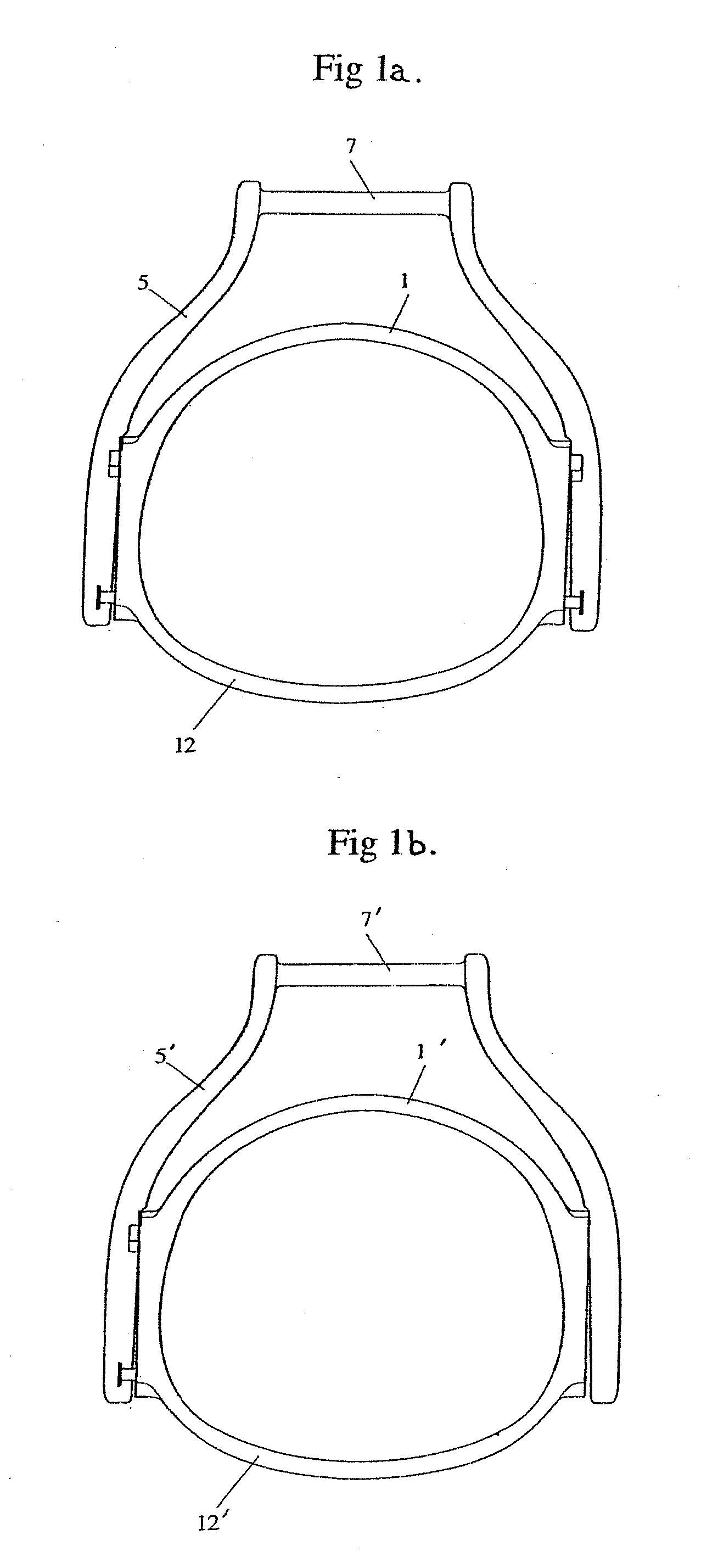
[0055]FIG. 1a shows an inverted U-shaped mounting member (5) comprising a horizontal bar (7) to which the stirrup strap may be attached. Located within the U-shaped mounting member is a D-shaped foot support (1) for receiving a rider's foot, including a footplate (12) which rests against the sole of the rider's boot.

[0056] When the stirrup is in normal use, the foot support (1) lies in the same plane as the U-shaped mounting member (5) and is held in place by two mountings located on either side of the U-shaped mounting member. In the embodiment shown in FIG. 1a, the projections of the mountings and two additional projections are all located on the foot support (1).

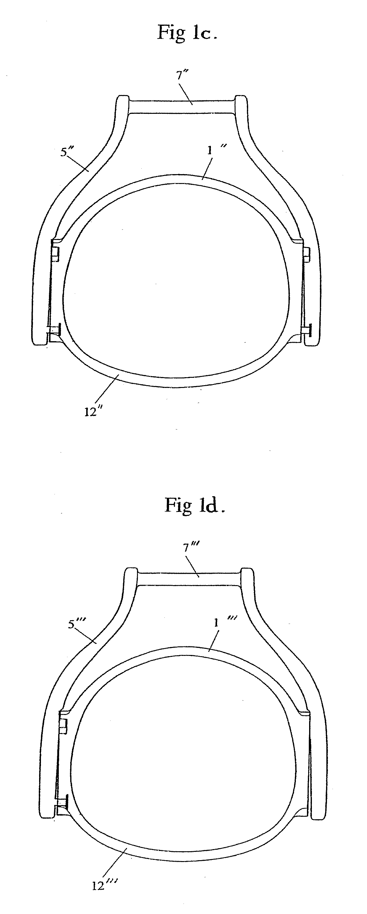
[0057]FIG. 1b again shows an inverted U-shaped mounting member (5′) comprising a horizontal bar (7′). Located within the U-shaped mounting member is a D-shaped foot support (1′) including a footplate (12′). In this embodiment there is one mounting, the projection and additional projection being located on the foot suppo...


PUM


Abstract

The invention provides a two-way safety stirrup that will release in the event of the rider being dismounted but which is less prone to unexpected release when pressure is applied in the forward direction. The safety stirrups are of far simpler construction than stirrups of the prior art, yet are not as prone to unexpected release and can be made of non-metal materials, such as plastics and polymers, so that the stirrups are more economically manufactured and are of comparatively light weight.

Description

CROSS REFERENCE TO RELATED APPLICATIONS [0001] This application is a continuation-in-part of U.S. patent application Ser. No. 10 / 756,832, filed Jan. 12, 2004, which is a continuation-in-part of U.S. patent application Ser. No. 10 / 048,078, filed Jul. 20, 2000,now U.S. Pat. No. 6,698,169, which is a National Phase filing under 35 U.S.C. §371 of PCT AU00 / 00867, which claims priority to Australian patent application PQ1803, filed Jul. 23, 1999, the entire disclosures of which are incorporated herein by this reference.FIELD OF THE INVENTION [0002] The present invention relates to a horse riding stirrup. In particular, the present invention relates to a safety stirrup which prevents the rider's foot being retained in the stirrup in the event of the rider being dismounted or thrown from the horse. More particularly, the present invention relates to a novel two-way release safety stirrup. BACKGROUND OF THE INVENTION [0003] Stirrups are well known in the prior art and have been used for hund...

Claims


Application Information

Patent Timeline
IPC IPC(8): B68C3/00
CPCB68C3/02
Inventor BOSTOCK, HAYDEN
Owner BOSTOCK DEV
Why Eureka
Try Eureka