Techniques for microchannel cooling

a technology of microchannels and cooling pipes, applied in the direction of laminated elements, lighting and heating apparatus, semiconductor/solid-state device details, etc., can solve the problems of fundamental limits to the amount of heat that a heat pipe of a given geometry can transport, and the inability to exploit the advancement, so as to reduce the pressure drop and adjust the efficiency of heat transfer

Active Publication Date: 2007-04-17
LUCENT TECH INC
View PDF12 Cites 79 Cited by
  • Summary
  • Abstract
  • Description
  • Claims
  • Application Information

AI Technical Summary

Benefits of technology

[0010]In an illustrative embodiment, the posts comprise nanoposts. Further, the nanoposts may receive a hydrophobic coating forming superhydrophobic nanostructures. The dimension, pitch and composition of these superhydrophobic nanostructures may be adjusted to reduce a pressure drop associated with pumping fluid through the microchannels and / or adjust the efficiency of heat transfer.

Problems solved by technology

Since advances in semiconductor, laser and power conversion technology are inevitably accompanied by higher powers and higher power densities, such advances cannot be exploited without concomitant advances in thermal management technologies.
Thus, thermal management has emerged as a primary limiting design factor in electronic systems.
However, since heat pipes are passive devices, relying on surface tension to circulate the heat-transfer fluid, there are fundamental limits to the amount of heat that a heat pipe of a given geometry can transport.
One problem with conventional microchannel cooling, however, is that the pressure drop associated with pumping fluid through a microchannel is very high since the channels are so small.
As a result, higher power fluid pumps, which are typically larger, heavier, more expensive and more complicated, are needed to overcome the drop.
Another problem associated with conventional microchannel cooling is that the efficiency of heat transfer to the fluid remains constant along the length of the microchannel.
Hot spot mitigation is a formidable problem faced by the electronics industry.
The result is that, increasingly, the hot regions on a die are very localized and limit the power that can be dissipated by the electronics.
These limitations further limit the functionality of the die.

Method used


Image

  • Techniques for microchannel cooling
  • Techniques for microchannel cooling
  • Techniques for microchannel cooling

Examples


Embodiment Construction

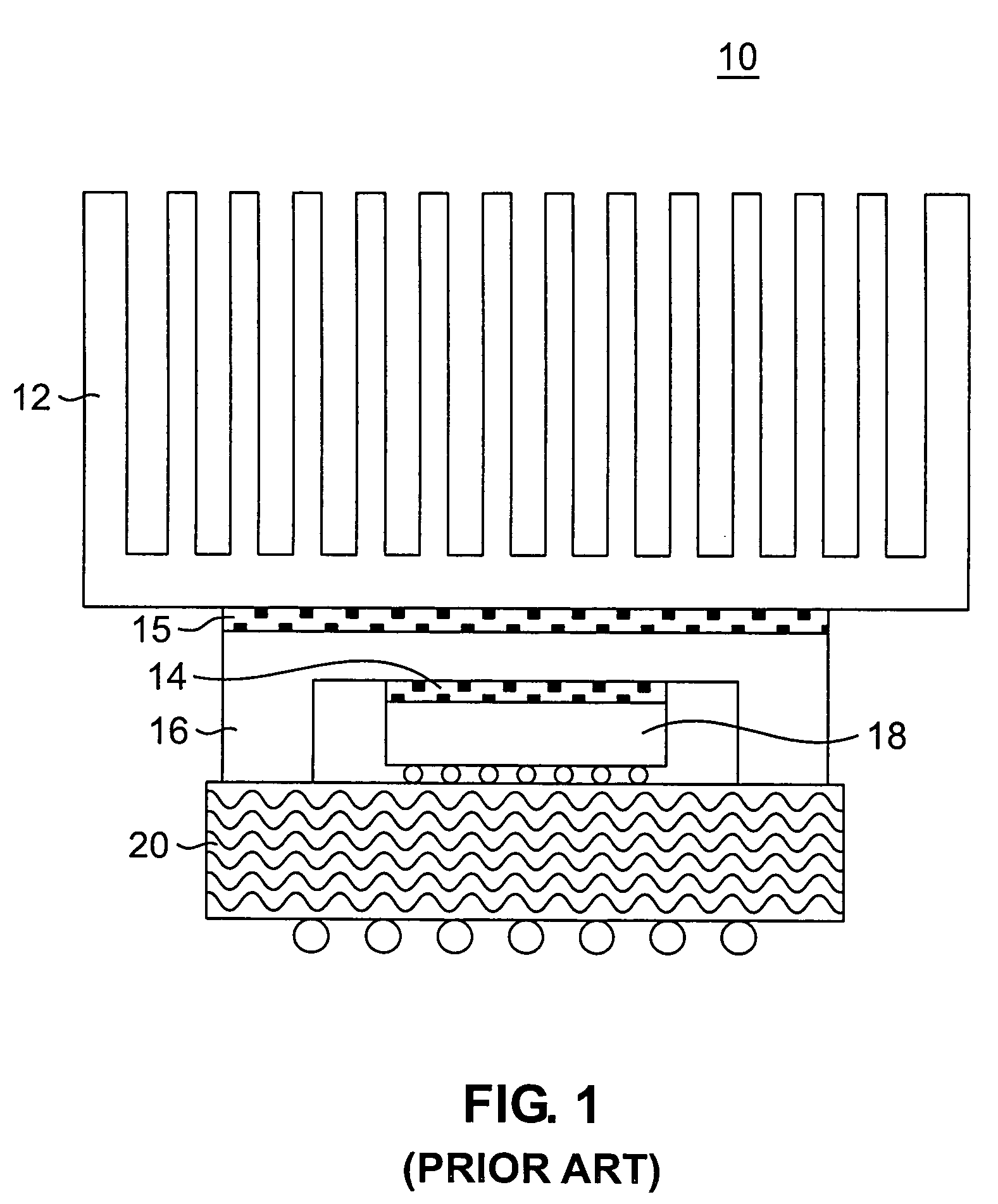
[0019]Prior to describing the inventive aspects and features of the present techniques, a conventional heat-transfer device will first be described. FIG. 1 is a diagram illustrating a conventional heat-transfer device. As shown in FIG. 1, conventional heat-transfer device 10 comprises heat sink 12, thermal interface materials (TIMs) 14 and 15, heat spreader 16, integrated circuit (IC) die 18 (heat source) and ball grid array (BGA) substrate 20. Such a heat-transfer device may comprise, by way of example, a central processing unit (CPU) of a personal computer (PC).

[0020]Heat spreader 16 may comprise a block of high thermal conductivity material, including, but not limited to, copper or an alloy thereof. Alternatively, heat spreader 16 may comprise a vapor chamber. A vapor chamber is a flat, hollow plate with internal structures that make it function like a heat pipe. For example, with the highest power devices, e.g., outputting 100 Watts or greater, heat spreader 16 may be constructe...


PUM

PropertyMeasurementUnit
temperatureaaaaaaaaaa
lengthaaaaaaaaaa
thicknessaaaaaaaaaa

Abstract

Techniques for heat transfer are provided. In one aspect of the invention, a heat-transfer device is provided. The heat-transfer device comprises one or more microchannels suitable for containing a heat-transfer fluid, one or more of the microchannels having protruding structures on at least one inner surface thereof configured to affect flow of the heat-transfer fluid through the one or more microchannels. The structures may comprise posts coated with a hydrophobic coating.

Description

FIELD OF THE INVENTION[0001]This invention relates generally to fluid mechanics and heat transfer and, more specifically, to techniques for thermal management in integrated circuits and other applications.BACKGROUND OF INVENTION[0002]Since advances in semiconductor, laser and power conversion technology are inevitably accompanied by higher powers and higher power densities, such advances cannot be exploited without concomitant advances in thermal management technologies. Thus, thermal management has emerged as a primary limiting design factor in electronic systems.[0003]Personal computers (PCs) provide an excellent example of a thermal management challenge. Namely, with the desktop PCs of today, average heat fluxes experienced can be greater than 150 Watts per square centimeter and in localized regions, often referred to as hot spots, significantly larger average heat fluxes can occur, potentially as high as 500 Watts per square centimeter.[0004]Research on the liquid cooling of ele...

Claims


Application Information

Patent Timeline
Patent Type & Authority Patents(United States)
IPC IPC(8): F28F13/00
CPCF28F3/048F28F3/12H01L23/473F28F2245/04F28F2260/02H01L2224/16225H01L2224/48091H01L2224/48227H01L2224/73253H01L2924/15311H01L2924/1532H01L2924/3011H01L2924/00014H01L24/48H01L2924/01019H01L2924/12041H01L2924/10253H01L2924/00H01L2924/12042H01L2924/14H01L2924/16152H01L2924/181H01L2924/00011
Inventor HODES, MARC SCOTTKOLODNER, PAUL ROBERTKRUPENKIN, THOMAS NIKITALEE, WONSUCKLYONS, ALAN MICHAELSALAMON, TODD RICHARDTAYLOR, JOSEPH ASHLEYWEISS, DONALD P.
Owner LUCENT TECH INC
Why Eureka
Try Eureka