Expandable fluoropolymer device for delivery of therapeutic agents and method of making

a fluoropolymer and balloon technology, applied in the direction of dilators, catheters, other domestic objects, etc., can solve the problems of difficult control of the flow rate and uniform delivery of fluid through the balloon walls, the inability of the therapeutic agent to properly penetrate the tissue at the treatment site, and the inability to effectively deliver the fluid. , to achieve the effect of effective delivery of fluid

Inactive Publication Date: 2005-10-18
ATRIUM MEDICAL
View PDF134 Cites 167 Cited by
  • Summary
  • Abstract
  • Description
  • Claims
  • Application Information

AI Technical Summary

Benefits of technology

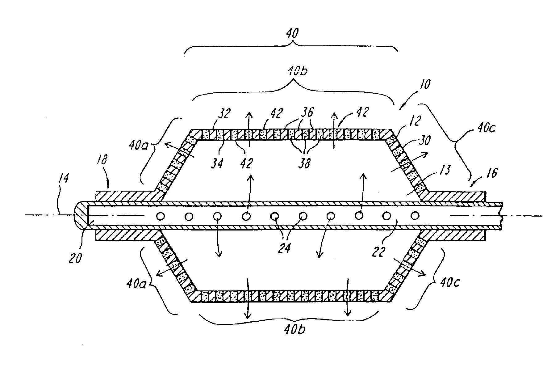
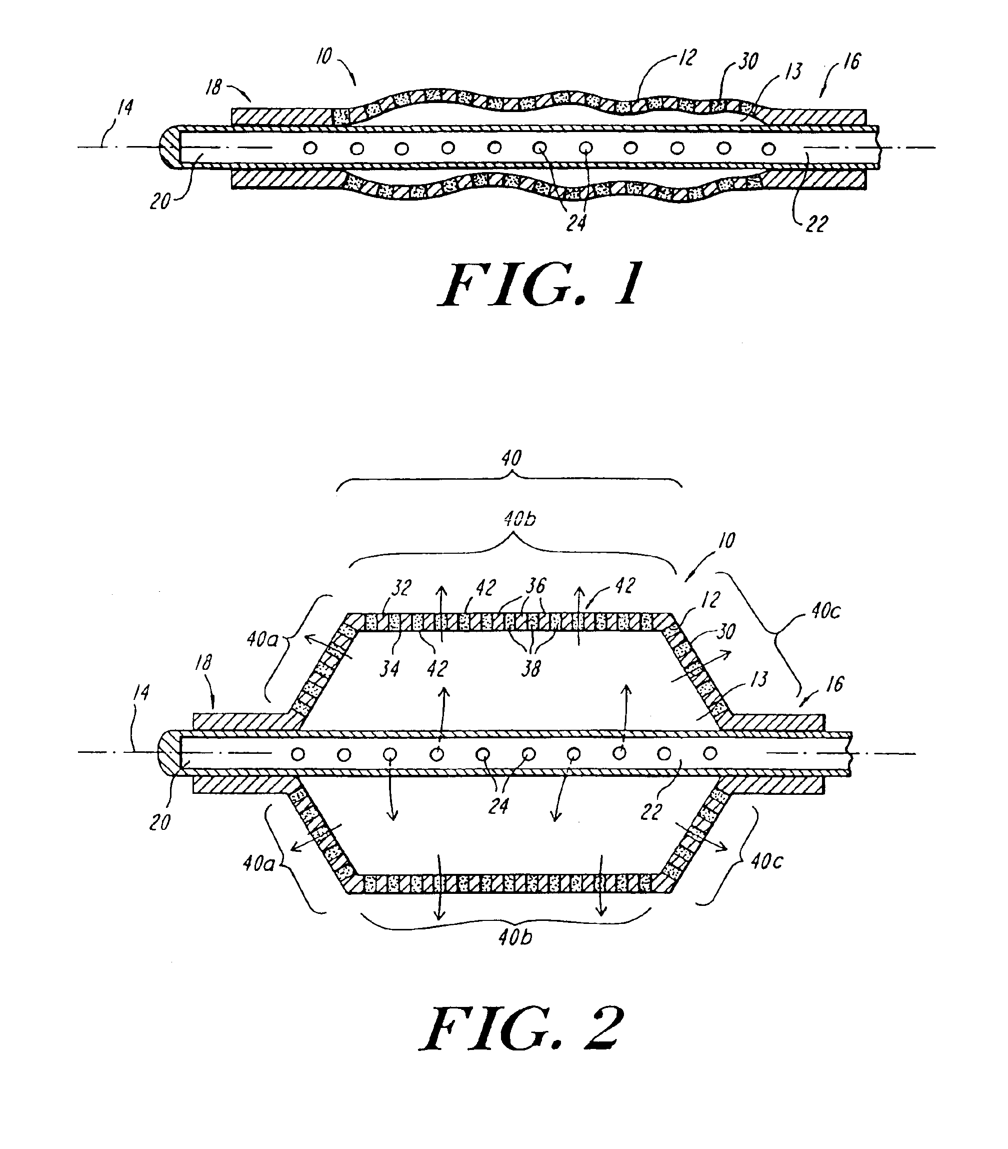
[0004]The present invention provides a radially expandable fluid delivery device for delivering fluid to a treatment site within the body. The radially expandable fluid delivery device can be used, for example, as a catheter delivered balloon for the treatment of body lumens, organs, and grafts. Fluids, including therapeutic agents, can be delivered through the walls of the fluid delivery device to effect localized treatment of sites within the body. The fluid delivery device of the present invention is constructed of a biocompatible material having a microstructure that can provide a controlled, uniform, low-velocity distribution of fluid through the walls of the fluid delivery device to effectively deliver the fluid to the treatment site without damaging tissue proximate the walls of the device.
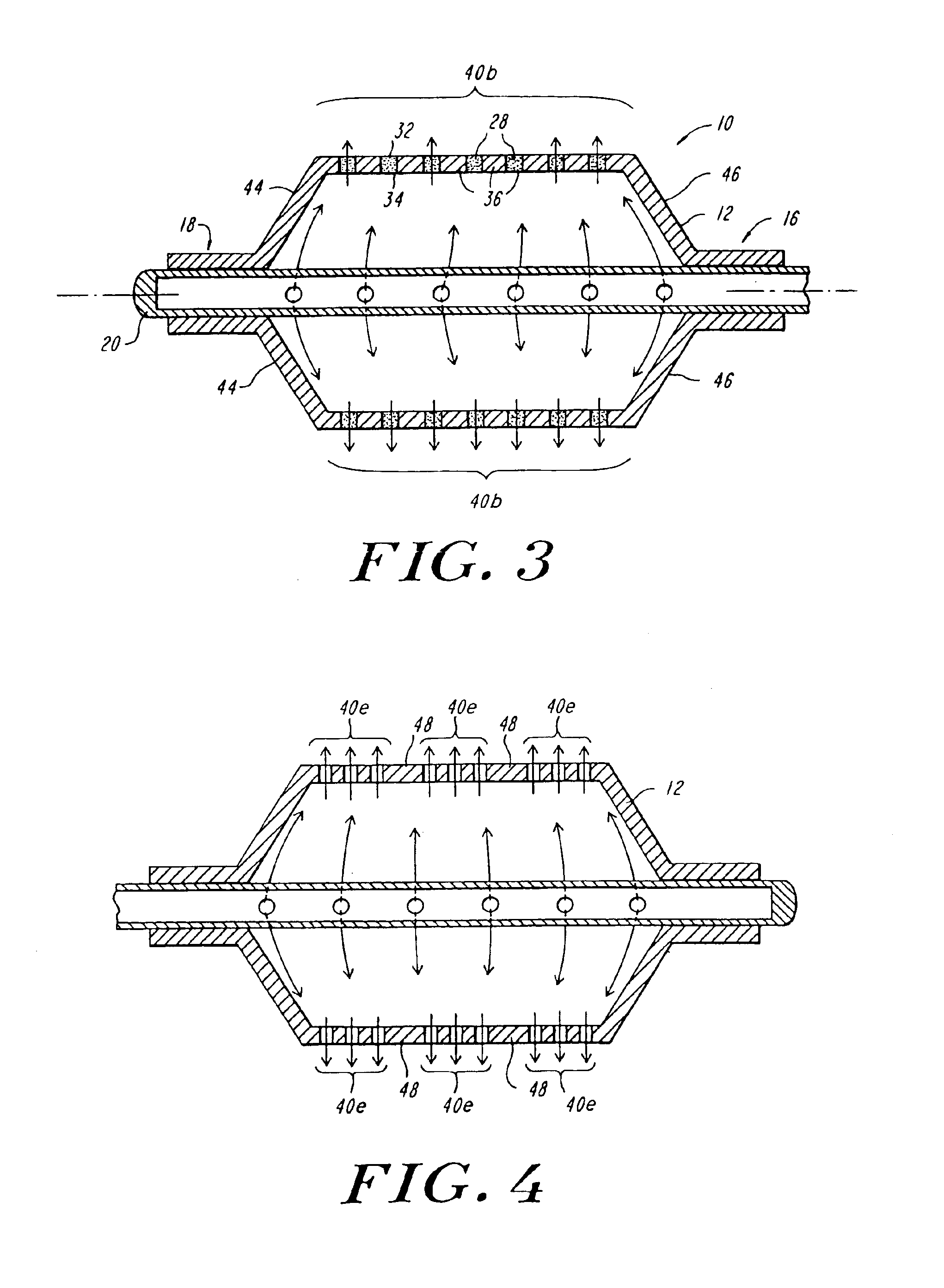
[0006]In accordance with another aspect of the present invention, the nodes within the microporous portion of the member can be oriented substantially parallel to the longitudinal axis of the member. The micro-channels are preferably sized to permit the passage of the pressurized fluid from the inner surface to the outer surface of the wall. The size of the microchannels within the microporous portion can be varied longitudinally and / or circumferentially to provide regions of increased porosity within the microporous portion. The presence of regions of differing porosity allows the volume of fluid delivered through the microporous portion of the member to vary, longitudinally and / or circumferentially, across the microporous portion. This allows the microporous portion to be specifically tailored to the size and shape of the site being treated.
[0008]In accordance with a further aspect of the present invention, the member can be provided with first and second microporous portions, each having a porosity sufficient for the pressurized fluid to permeate through the wall of the member. The first and second microporous portions can be spaced apart longitudinally and / or circumferentially. An impermeable or semipermeable portion can be interposed between the first and second microporous portions. Further microporous portions and / or impermeable or semi-permeable portions can also be provided on the member. The microporous portions and the impermeable portions can be arranged in numerous alternative configurations. For example, microporous ring-shaped portions can be spaced along the longitudinal axis of the member. Alternatively, the microporous portions can be generally rectangular in shape and can be spaced apart about the circumference of the member. The provision of multiple microporous portions allows the fluid delivery device of the present invention to treat multiple sites within the body simultaneously.
[0015]The step of radially expanding the expanded fluoropolymer tube can also include the steps of positioning the tube within the internal cavity of a mold fixture and radially expanding the balloon within the tube while the tube remains positioned in the internal mold cavity. The internal mold cavity preferably has a size and shape analogous to the predefined size and shape of the balloon. The internal cavity of the mold facilitates concentric radial expansion of the balloon and the fluoropolymer tube.

Problems solved by technology

A problem common to such conventional catheter balloons is that the flow-rate and the uniform delivery of fluid, and hence the therapeutic agent, through the walls of the balloon is difficult to control.
If the flow rate is too low, the therapeutic agent can fail to properly penetrate the tissue at treatment site.
If the flow rate is too high, the therapeutic agent can be delivered to areas of the body outside of the treatment area and, in some cases, elevated flow rates can result in the formation of high velocity fluid jets which can traumatize the tissue adjacent the walls of the balloon.

Method used


Image

  • Expandable fluoropolymer device for delivery of therapeutic agents and method of making
  • Expandable fluoropolymer device for delivery of therapeutic agents and method of making
  • Expandable fluoropolymer device for delivery of therapeutic agents and method of making

Examples


example 1

[0085]An exemplary fluid delivery device was constructed according to the manufacturing processes of the present invention by employing 0.068″ (ID) / 0.088″ (OD) ePTFE tubing. The longitudinal stretch ratio of the ePTFE tube was 1.5: 1, at a stretch rate of 10 inches per second. An electron micrograph of an exterior section of a sample ePTFE tube, after stretching, is shown in FIG. 14A. FIG. 14A illustrates the microstructure of nodes interconnected by fibils of the ePTFE tubing and, in particular, the orientation of the nodes generally perpendicular to the longitudinal axis of the tubing and the intemodal through-pores. An 8 mm×8 cm PET balloon was employed to radially expand the ePTFE tubing. The PET balloon was attached to a vacuum source and a slight vacuum was placed on the PET balloon, about −5 to −10 psi. The ePTFE tubing was then positioned over the deflated PET balloon. The PET balloon and the ePTFE tubing were then connected to a hypo-tube and placed into a water heated cham...

example 2

[0088]Three ePTFE synthetic grafts were treated using an ePTFE diffusion balloon constructed in accordance with the method of Example 1 to determine the permeability of a contrast agent into the grafts. The diffusion balloon employed was 8 cm in length, had an OD of 6 mm and was constructed from an 0.088″ (OD) / 0.068″ (ID) ePTFE tube having a stretch ratio of 1.5:1. Each of the grafts treated was an Atrium Hybrid PTFE graf model no. 01200670, available from Atrium Medical of Hudson, N.H. The grafts had a 6mm inner diameter and a wall thickness of 0.025 inches. In each case, the balloon was inserted into a graft and inflated by infusing a contrast agent. The balloon was inflated to 1 atm. by the infused fluid. The balloon was then removed from the graft and the graft was flushed with water delivered at 500 ml / min. The contrast agent used was Hypaque-76 available from Mycomed, Inc. Table 1 summarizes each procedure.

[0089]

TABLE 1Duration of BalloonBalloon InfusionGraft FlushingGraft Sam...

example 3

[0093]The permeability of several ePTFE fluid delivery devices constructed in accordance with the manufacturing processes of the present invention was evaluated and compared with the permeability of selected synthetic grafts. Each of the fluid delivery devices was constructed from an extruded and expanded ePTFE tube as set forth in

[0094]Table 3.

[0095]

TABLE 3FluidStretchWallDeliveryRatioStretch Rate ofThickness ofSurface Area ofDeviceof ePTFEePTFE tubeFluid DeliveryFluid DeliverySampletube(in / s)Device (in)Device (in2)11.5:1200.00680.45621.75:1 100.00550.4693  3:1100.0050.4694  5.1100.0030.50351.25:1 100.00750.39961.5:10.50.00550.39971.5:1100.0050.39981.5:1100.0050.29

[0096]The synthetic grafts analyzed were standard and thin wall grafts available from Atrium Medical Corporation and W. L. Gore & Associates, Inc. Information regarding the grafts in Table 4

[0097]

TABLE 4Graft sampleTypeWall Thickness (in)Surface Area (in2)AAtrium 6 mm std0.0250.964BAtrium 6 mm thin0.0220.963CGore 7 mm thi...


PUM

PropertyMeasurementUnit
pressureaaaaaaaaaa
flow rateaaaaaaaaaa
widthaaaaaaaaaa

Abstract

A radially expandable fluid delivery device for delivering a fluid to a treatment site within the body is disclosed. The fluid delivery device is constructed of a microporous, biocompatible fluoropolymer material having a microstructure that can provide a controlled, uniform, low-velocity fluid distribution through the walls of the fluid delivery device to effectively deliver fluid to the treatment site without damaging tissue proximate the walls of the device. The fluid delivery device includes a tubular member defined by a wall having a thickness transverse to the longitudinal axis of the tubular member and extending between an inner and an outer surface. The wall is characterized by a microstructure of nodes interconnected by fibrils. The tubular member is deployable from a first, reduced diameter configuration to a second, increased diameter configuration upon the introduction of a pressurized fluid to the lumen. The tubular member includes at least one microporous portion having a porosity sufficient for the pressurized fluid to permeate through the wall. Substantially all of the nodes within the microporous portion are oriented such that spaces between the nodes form micro-channels extending from the inner surface-to the outer surface of the wall.

Description

REFERENCE TO RELATED APPLICATIONS[0001]This application claims priority to Provisional Application Ser. No. 60 / 117,152, filed Jan. 25, 1999, and incorporated herein by reference.BACKGROUND OF THE INVENTION[0002]Catheter delivered inflatable balloons are utilized in a wide range of surgical procedures to dilate, obstruct, or restore patency to body vessels and organs, as well as to maintain the position of catheter delivered instruments in vivo. Such balloons are typically attached to the distal tip of a small diameter catheter tube to facilitate delivery of the balloon to a treatment site within the body. The balloon is advanced by the catheter through a body vessel while in a deflated condition until the balloon is appropriately positioned proximate the treatment site. The balloon is inflated by infusing a fluid, such as saline, a contrast media, or water, into the balloon through an inflation lumen provided in the catheter. The inflated balloon is deflated after treatment and subs...

Claims


Application Information

Patent Timeline
Patent Type & Authority Patents(United States)
IPC IPC(8): A61L29/00A61L29/04B29C55/24B29C55/00A61M25/10B29C47/00A61F2/958B29C48/00B29C48/09
CPCA61L29/041A61M25/1029B29C47/0023B29C55/24C08L27/18A61M25/10B32B2305/026A61M2025/0057A61M2025/105A61M2025/1075B29C47/00B29C2049/465B29K2027/18B29L2022/022B29L2031/753B29C48/09B29C48/00
Inventor HERWECK, STEVE A.GINGRAS, PETER H.MARTAKOS, PAULKARWOSKI, THEODORE
Owner ATRIUM MEDICAL
Why Eureka
Try Eureka