Electrical switch

A technology for electrical switches and disconnection positions, applied in the direction of electrical switches, high-voltage/high-current switches, electrical components, etc., can solve the problems of damaged arc parts, arc erosion, etc., and achieve the effect of compact cost

Active Publication Date: 2019-11-01
ABB (SCHWEIZ) AG
View PDF8 Cites 0 Cited by
  • Summary
  • Abstract
  • Description
  • Claims
  • Application Information

AI Technical Summary

Problems solved by technology

The arc is aggressive and therefore can damage components in the vicinity of the arc

Method used


Image

  • Electrical switch
  • Electrical switch
  • Electrical switch

Examples


Embodiment Construction

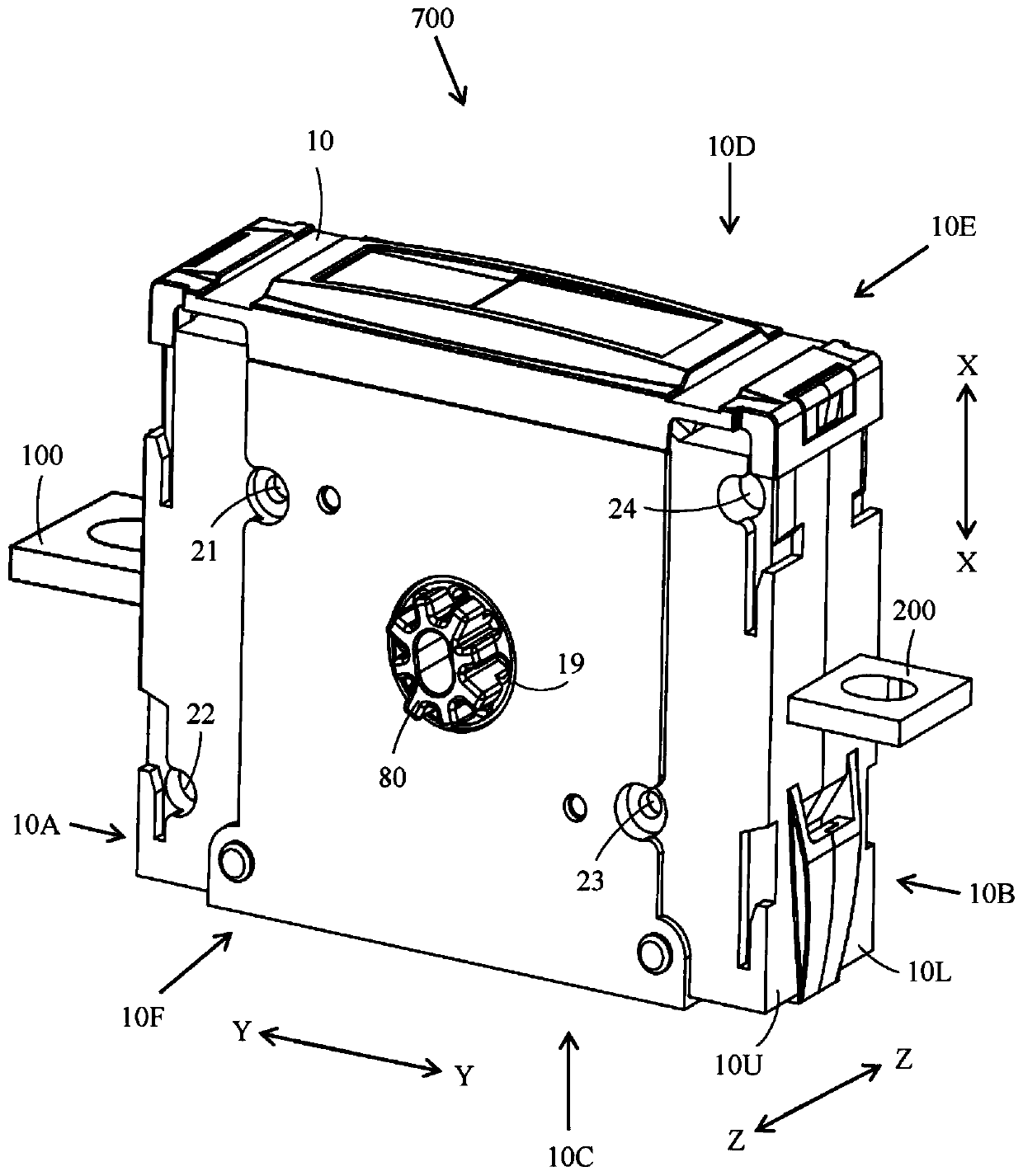
[0044] figure 1 An isometric view of an electrical switch is shown.

[0045] The electrical switch 600 includes a housing 10 having a longitudinal direction Y-Y, a height direction X-X perpendicular to the longitudinal direction Y-Y, and a thickness direction Z-Z perpendicular to the longitudinal direction Y-Y and perpendicular to the height direction X-X. The height direction X-X and the thickness direction Z-Z form a transverse direction with respect to the longitudinal direction Y-Y of the casing 10 .

[0046] Housing 10 includes two halves 10L and 10U. The first half 10L of the housing 10 is placed against the second half 10U of the housing 10 such that a substantially closed space is formed within the two halves 10L, 10U. Each half 10L of the housing 10 includes side panels 10E, 10F and side walls 10A, 10B, 10C, 10D extending perpendicularly from peripheral edges of the side panels 10E, 10F. When the two halves 10L, 10U of the housing 10 are connected together, the outer...


PUM


Abstract

The invention provides an electrical switch. The electrical switch comprises at least one fixed contact (100, 200), a movable contact (300) contacting the fixed contact, and at least one extinguishingapparatus (14A, 14B) positioned after the fixed contact (100, 200) in an opening direction of the movable contact. A permanent magnet (510, 520) is further positioned after the extinguishing apparatus in the opening direction of the movable contact.

Description

technical field [0001] This invention relates to electrical switches. Background technique [0002] Various electrical switches with fixed contacts and movable contacts exist in the market. The movable contact forms the connection between the stationary contacts. An electrical switch may include fixed contacts and movable contacts that perform coupling and disconnection between the fixed contacts. A load can be connected to the fixed contact, and a power source can be connected to the other fixed contact. [0003] Electrical switches can be provided with bumper contacts or blade contacts. The contacts in the bumper contact structure are pressed to the fixed contacts. The movable contact may include a knife hinged at one end to the fixed contact, wherein the other end of the knife serves as a partition member. A knife contact configuration can also be achieved by openings at the opposite ends of the knife. A central portion of the blade may be connected to the rotating ...

Claims


Application Information

Patent Timeline
Patent Type & Authority Applications(China)
IPC IPC(8): H01H9/44H01H9/36
CPCH01H9/443H01H9/36H01H2009/365H01H1/2041H01H1/42H01H33/08H01H73/045H01H2001/425H01H2033/085H01H9/346H01H9/362
Inventor 斯特兰德·弗雷德里克索尔丹·尤哈林塔莫·尤卡瓦利瓦伊尼奥·米科
Owner ABB (SCHWEIZ) AG
Why Eureka
Try Eureka