
Panel lamp

A panel lamp and lampshade technology, applied in the directions of plane/plate light guide, plane light source, light guide of lighting device, etc., can solve the problems of poor comfort, light leakage, poor irradiation effect, etc., and achieve the effect of convenient installation and fixation and good irradiation effect.

Inactive Publication Date: 2019-11-05
NINGBO GANPE OPETOELECTRONICS
View PDF4 Cites 0 Cited by
  • Summary
  • Abstract
  • Description
  • Claims
  • Application Information

AI Technical Summary

Problems solved by technology

[0003] The side-emitting panel light includes a frame, a lamp board, a light guide plate, reflective paper, a lampshade, and a rib for supporting the lampshade. There is a certain gap between the light source on the lamp board and the light guide plate in the prior art, which will cause some Light leakage, and the light guide plate and the lampshade are fitted together, so the light leakage generated between the light source on the lamp board and the light guide plate will directly leak from the side of the lampshade, resulting in poor illumination effect, so the existing technology is to prevent this. If this situation occurs, the edge will be made wider, so that although the light leakage can be blocked, the wider edge will make the user less comfortable to use

Method used


Image

  • Panel lamp
  • Panel lamp

Examples


specific Embodiment 1

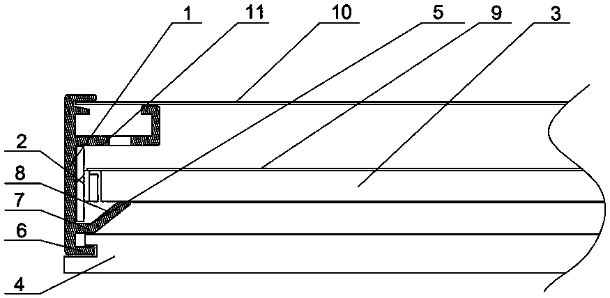
[0029] Specific embodiment one, such as figure 1 Shown: a panel lamp, including a frame 1, a lamp panel 2, a light guide plate 3, a lampshade 4, reflective paper 9, a backboard 10, and a rib 6 for supporting the lampshade 4, wherein:

[0030] The lamp board 2 includes a circuit board and a light emitting component, and the light emitting component is arranged opposite to the light guide plate 3, and irradiates the light generated by the light emitting component into the light guide plate 3;

[0031] The light guide plate 3 is used for injecting the light emitted by the light-emitting component;

[0032] The reflective paper 9 is arranged at the rear of the light guide plate 3, and the size of the reflective paper 9 is larger than the size of the light guide plate 3, and is used to reflect all the light rays entering the light guide plate 3;

[0033] The back panel 10 is arranged on the back of the panel light;

[0034] The lampshade 4 is arranged at the front of the panel la...

specific Embodiment 2

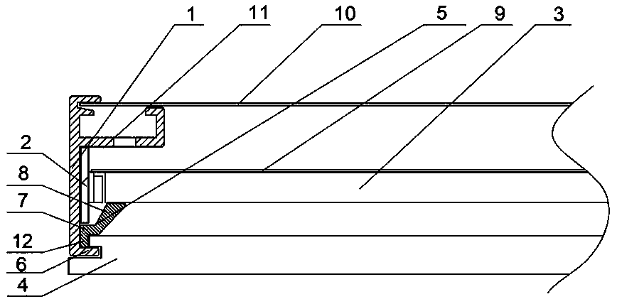
[0041] Specific embodiment two, such as figure 2 As shown, the difference from the first embodiment is that in the second embodiment, the support plate 11 and the rib 6 are integrally formed with the frame 1, but the support member 5 and the frame 1 are two different components and are not integrally formed together. , the lampshade 4 is provided with a first limiting groove, and the rib 6 is embedded in the first limiting groove for fixing, so that the lampshade 4 can be fixed on the rib 6, and the upper end of the first limiting groove of the lampshade 4 is provided with a protrusion, the protrusion There is a second limit slot between the frame and the frame 1, and the support 5 includes a vertical part 12, a horizontal part 7 and an inclined part 8 from bottom to top, and the vertical part 12 of the support 5 is embedded in the second limit slot Left and right limit, then the lower end of the vertical part 12 of the support 5 is against the rib 6, and the upper end of the...


PUM

PropertyMeasurementUnit
Slopeaaaaaaaaaa
Lengthaaaaaaaaaa

Abstract

The invention relates to the technical field of illumination lamps, in particular to a panel lamp. The panel lamp comprises a frame (1), a lamp panel (2), a light guide plate (3), reflective paper (9), a lampshade (4) and a blocking edge (6) used for supporting the lampshade (4), and the panel lamp is characterized in that a gap is formed between the light guide plate (3) and the lampshade (4). The panel lamp is good in illumination effect and comfortable to use.

Description

technical field [0001] The invention relates to the technical field of lighting fixtures, in particular to a panel light. Background technique [0002] Panel light is a kind of lighting fixture. There are two types of light emitting forms in the prior art, namely direct light emission and side light emission. Because the overall thickness of the direct light light panel light is relatively large, it is necessary to choose in some installation scenarios. Side-emitting panel light. [0003] The side-emitting panel light includes a frame, a lamp board, a light guide plate, reflective paper, a lampshade, and a rib for supporting the lampshade. There is a certain gap between the light source on the lamp board and the light guide plate in the prior art, which will cause some Light leakage, and the light guide plate and the lampshade are fitted together, so the light leakage generated between the light source on the lamp board and the light guide plate will directly leak from the ...

Claims


Application Information

Patent Timeline
IPC IPC(8): F21V1/14F21V17/10
CPCF21V1/143F21V17/104F21V2200/20F21Y2105/16F21S10/005F21V21/04F21V17/16F21S8/04G02B6/0088F21Y2115/10G02B6/0091G02B6/0055
Inventor 俞相军袁柳
Owner NINGBO GANPE OPETOELECTRONICS
Learn More