Supercharge Your Innovation With Domain-Expert AI Agents!

Device power supply monitoring method

A technology for power monitoring and equipment, which is applied in the field of equipment power monitoring that can switch equipment power at a set time, and can solve problems such as automatic completion, difficulty in realizing random value testing of power off time, and inability to accurately record power supply working status

Pending Publication Date: 2019-11-05
KUNSHAN LIANTAO ELECTRONICS CO LTD
View PDF6 Cites 0 Cited by
  • Summary
  • Abstract
  • Description
  • Claims
  • Application Information

AI Technical Summary

Problems solved by technology

[0003] Therefore, the existing solutions cannot automatically complete the loading of voltage input and output parameters of several groups of power supplies, the setting of power on time and / or off time after one-time setting, and cannot accurately record the working status of the power supply; it is difficult to realize the power supply Random value test for closing time

Method used


Image

  • Device power supply monitoring method
  • Device power supply monitoring method

Examples


Embodiment Construction

[0049] Below in conjunction with accompanying drawing, structural principle and working principle of the present invention are specifically described:

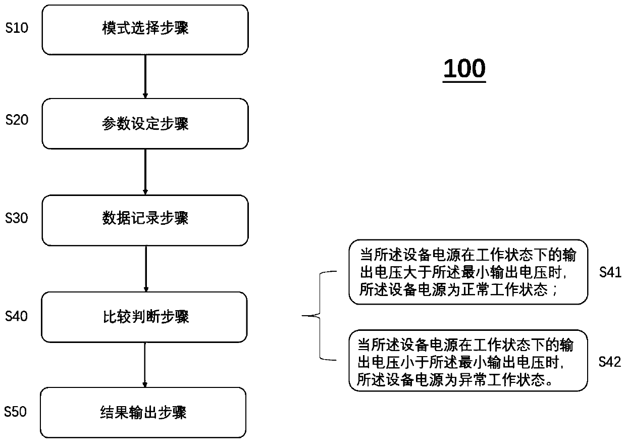
[0050] figure 1 It is a schematic flowchart of a monitoring method according to an embodiment of the present invention. Such as figure 1 As shown, the monitoring method includes steps S10-S50. Wherein, step S10 is used to select a mode, and choose to use the first mode or the second mode to monitor the power supply of the device. In the first mode, the device power is turned on or off at a fixed time, for example, if the device power is turned on and off for 3 seconds, then in actual operation, the device power is turned on and off for 3 seconds; In the second mode, the device power is turned on or off at random times. For example, if the device power is turned on and off for 3s and off for 3s, then in actual operation, the device power is turned on and off for 3s and 1.5s, 0.9s, 2.5s or 1.2s and so on. The shutdown time ...


PUM


Abstract

The invention provides a device power supply monitoring method. The monitoring method includes the steps of S10, mode selection, wherein a first mode or a second mode is selected for monitoring; S20,parameter setting, wherein working parameters of a device power supply are set; S30, data recording, wherein input-output data of the device power supply in a working state is recorded; S40, comparison and judgment, wherein the input-output data is compared with the working parameters, and the working state of the device power supply is judged; S50, result output, wherein the comparison and judgment result is output, and the working parameters include the on / off time of the device power supply.

Description

technical field [0001] The invention relates to a device power monitoring method, in particular to a device power monitoring method capable of switching the device power on and off at a set time. Background technique [0002] In the work of existing equipment, various power supplies require high reliability of each output when they are repeatedly input and powered off. For example, medical power supplies and special industrial power supplies require tens of thousands of switches with zero error rate. The existing solution is to set the list mode in the power supply (Input Source), complete the switching action by hardware, and use a recorder to measure and record the output voltage value of the power supply. [0003] Therefore, the existing solutions cannot automatically complete the loading of voltage input and output parameters of several groups of power supplies, the setting of power on time and / or off time after one-time setting, and cannot accurately record the working...

Claims


Application Information

Patent Timeline
IPC IPC(8): G01R31/40
CPCG01R31/40
Inventor 李光旭
Owner KUNSHAN LIANTAO ELECTRONICS CO LTD
Features
  • R&D
  • Intellectual Property
  • Life Sciences
  • Materials
  • Tech Scout
  • Unparalleled Data Quality
  • Higher Quality Content
  • 60% Fewer Hallucinations
Learn More