Cable end holding device for holding cable end, method for positioning cable end of cable, and cable bundling machine

A technology for holding devices, clustering machines, applied in the direction of cable installation devices, equipment for connecting/terminating cables, installation of cables, etc.

Active Publication Date: 2019-11-05
科迈士瑞士股份有限公司
View PDF6 Cites 0 Cited by
  • Summary
  • Abstract
  • Description
  • Claims
  • Application Information

AI Technical Summary

Problems solved by technology

In addition, in the prior art, each tool must be set to a height that guarantees an internal clear...

Method used


Image

  • Cable end holding device for holding cable end, method for positioning cable end of cable, and cable bundling machine
  • Cable end holding device for holding cable end, method for positioning cable end of cable, and cable bundling machine
  • Cable end holding device for holding cable end, method for positioning cable end of cable, and cable bundling machine

Examples


Embodiment Construction

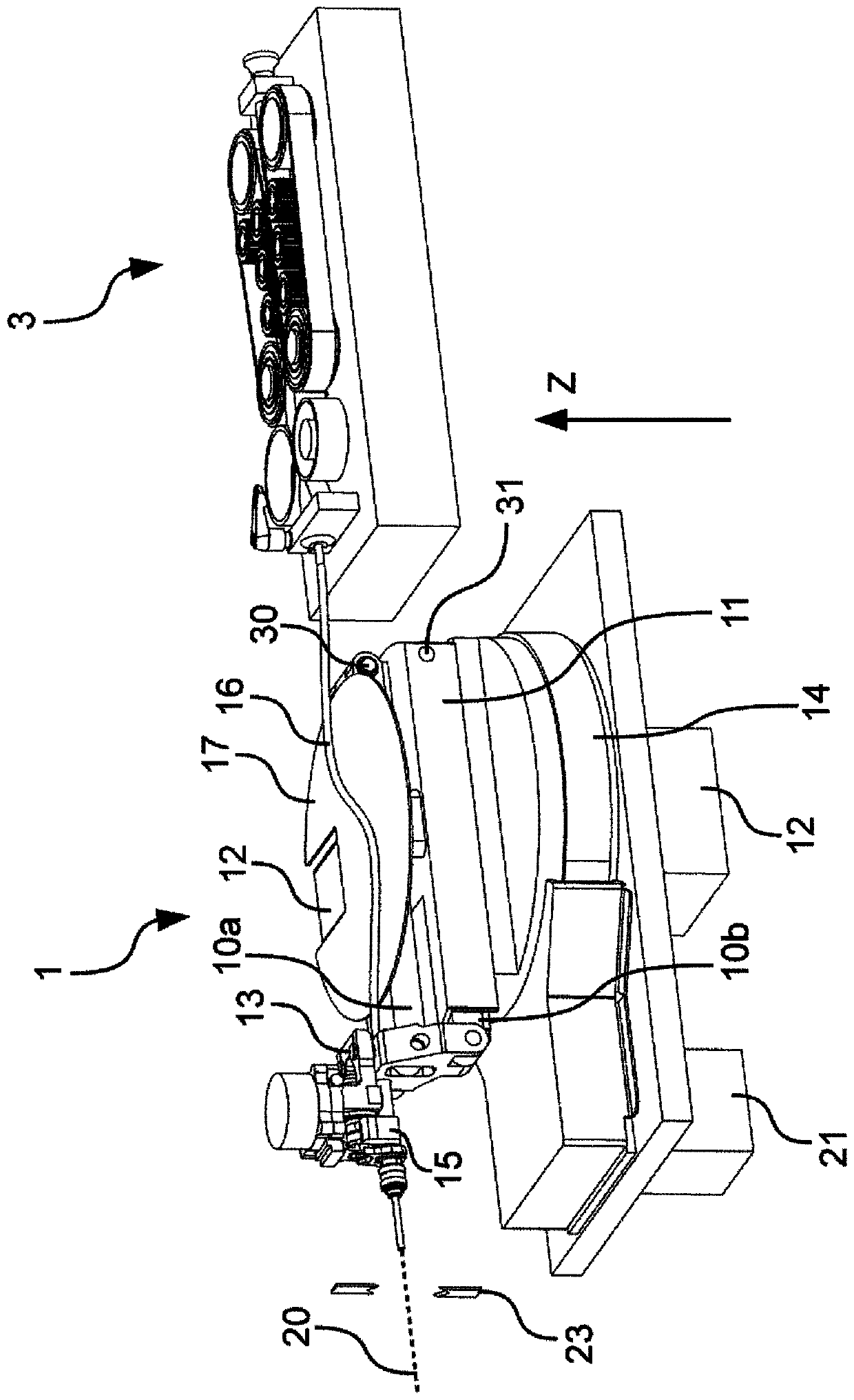
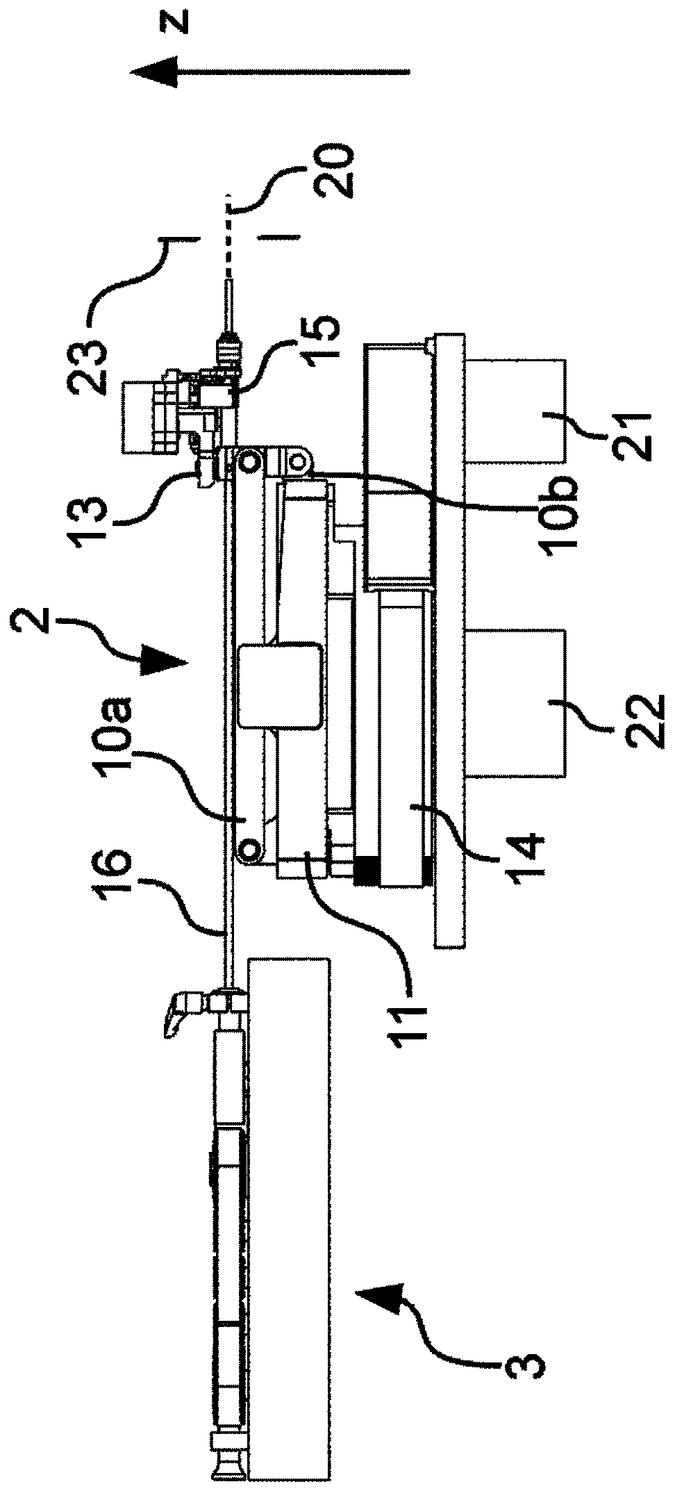
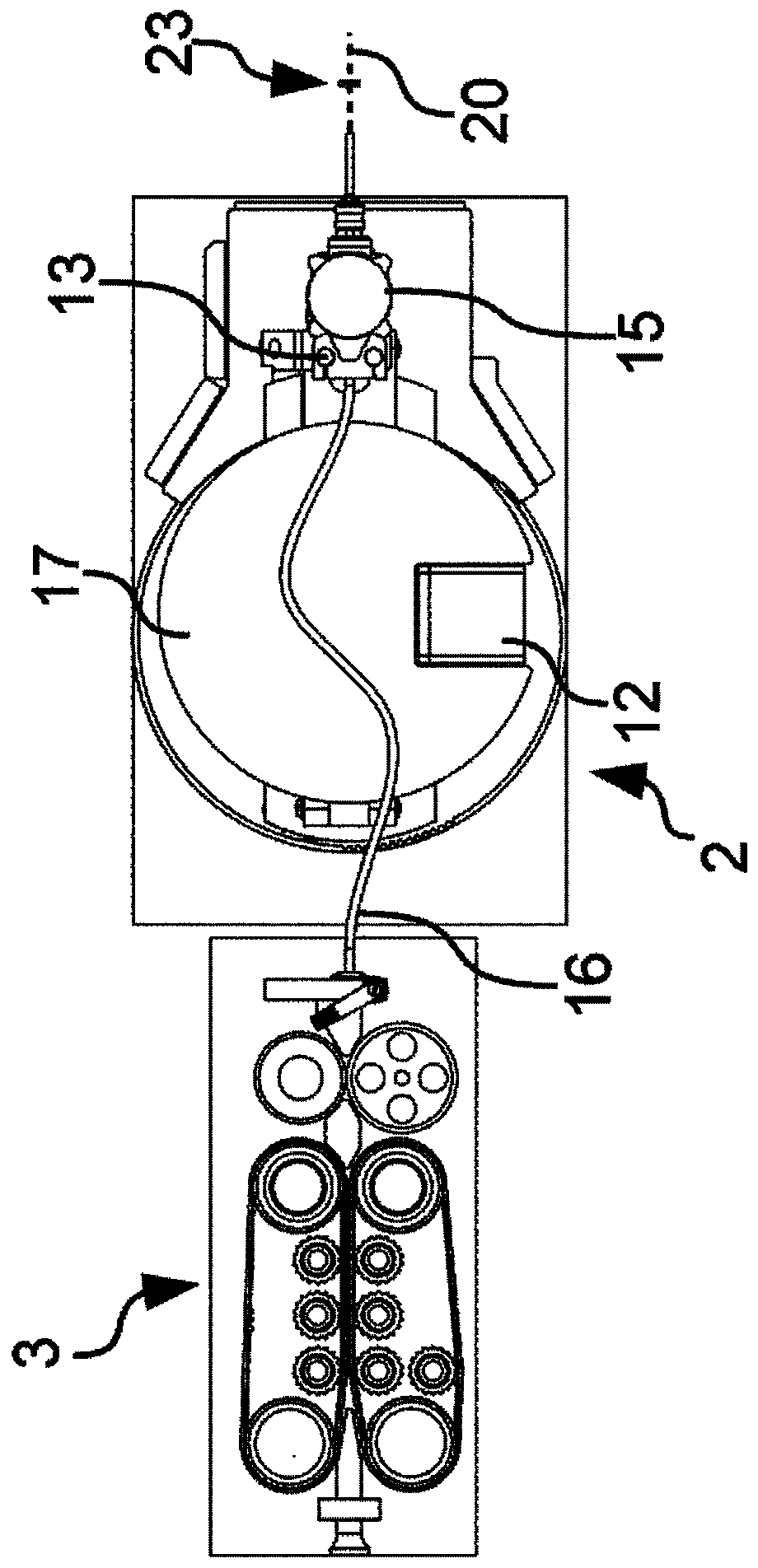
[0045] The cable end holding device 1 has a pivot arm 2 and a cable holding element 15 for holding a cable end 25 or a cable tip of a cable. Pivot arm 2 can make cable retaining member 15 rotate around vertical axis, and along longitudinal direction (in figure 2 extending from left to right in ) and in height direction (in figure 2 extending from the bottom to the top) changes.

[0046] The cable holding element 15 holds the cable end 25 or cable tip, ie the end of the cable. The outermost tip or end of the cable protrudes from the cable holding element 15 on the side of the cable holding element 15 facing away from the pivot arm 2 .

[0047] The cable end 25 or cable tip is generally not the outermost end of the cable. The cable end 25 or cable tip is the part of the cable that is located near the outermost end of the cable. The outermost end of the cable can, for example, be grasped or held by the cable holding element 15 at a distance of about 0.5 cm to about 5 cm, in...


PUM


Abstract

The invention relates to a cable end holding device (1). The invention relates to a cable end (25) for holding a cable for a crimping process. The cable end holding device (1) comprises: a cable end holding device (1); a cable holding element (15)for holding a cable end; and a height position changing device which comprises two rod elements (10a, 10b). The rod elements are used for changing the height position of the cable holding element (15) independently of the movement of the punch in the crimping process. The rod elements (10a, 10b) are arranged parallel to each other in the longitudinaldirection of the rod elements (10a, 10b), wherein the rod elements (10a, 10b) are arranged offset from each other in the vertical direction and in the width direction perpendicular to the vertical direction and to the longitudinal direction, and wherein the rod elements (10a, 10b) are each rotatably mounted about a first axis of rotation (30, 31) extending in the width direction, the two first axes of rotation (30, 31) extending parallel to each other.

Description

technical field [0001] The invention relates to a cable end holding device for holding a cable end of a cable, a method for positioning a cable end of a cable, and a cable bundling for bundling cables machine. Background technique [0002] Various cable tying machines for holding cable ends of cables are known. Figure 10 A top view of a known cable bundling machine with a press 5' or crimping press is shown, Figure 11 A side view thereof is shown, the press comprising an anvil 27' and a punch 24' for connecting the contact element 26' to the cable end, or a cable end retaining device according to the prior art . The cable binding machine includes two additional stations 6', 6", where cables or cable ends can be changed further. [0003] A cable bundling machine with a pivoting arm, known for example from EP 2 937 953 B1, comprising: a cable end holding device 1' for holding the cable ends of the cables. In this case, the cable end is held by a vertically movable grippi...

Claims


Application Information

Patent Timeline
IPC IPC(8): H01R43/048H01R43/05H01R43/052
CPCH01R43/0488H01R43/05H01R43/052H01R43/28H01R43/058Y10T29/5193Y10T29/5142Y10T29/514Y10T29/49192Y10T29/53235Y10T29/53261B25J9/1065H02G1/1256H02G1/14
Inventor 史蒂芬·维维罗利
Owner 科迈士瑞士股份有限公司
Why Eureka
Try Eureka