
Motor

A technology of motors and sleeves, applied in the field of motors with good assembly convenience, can solve the problems of complicated assembly procedures of motors 9, difficulty in improving assembly efficiency, and difficulty in coaxiality correction, so as to improve operation convenience and efficiency, reduce Technical threshold, the effect of coaxiality correction is easy to carry out

Inactive Publication Date: 2019-11-05
SUNONWEALTH ELECTRIC MACHINE IND
View PDF6 Cites 0 Cited by
  • Summary
  • Abstract
  • Description
  • Claims
  • Application Information

AI Technical Summary

Problems solved by technology

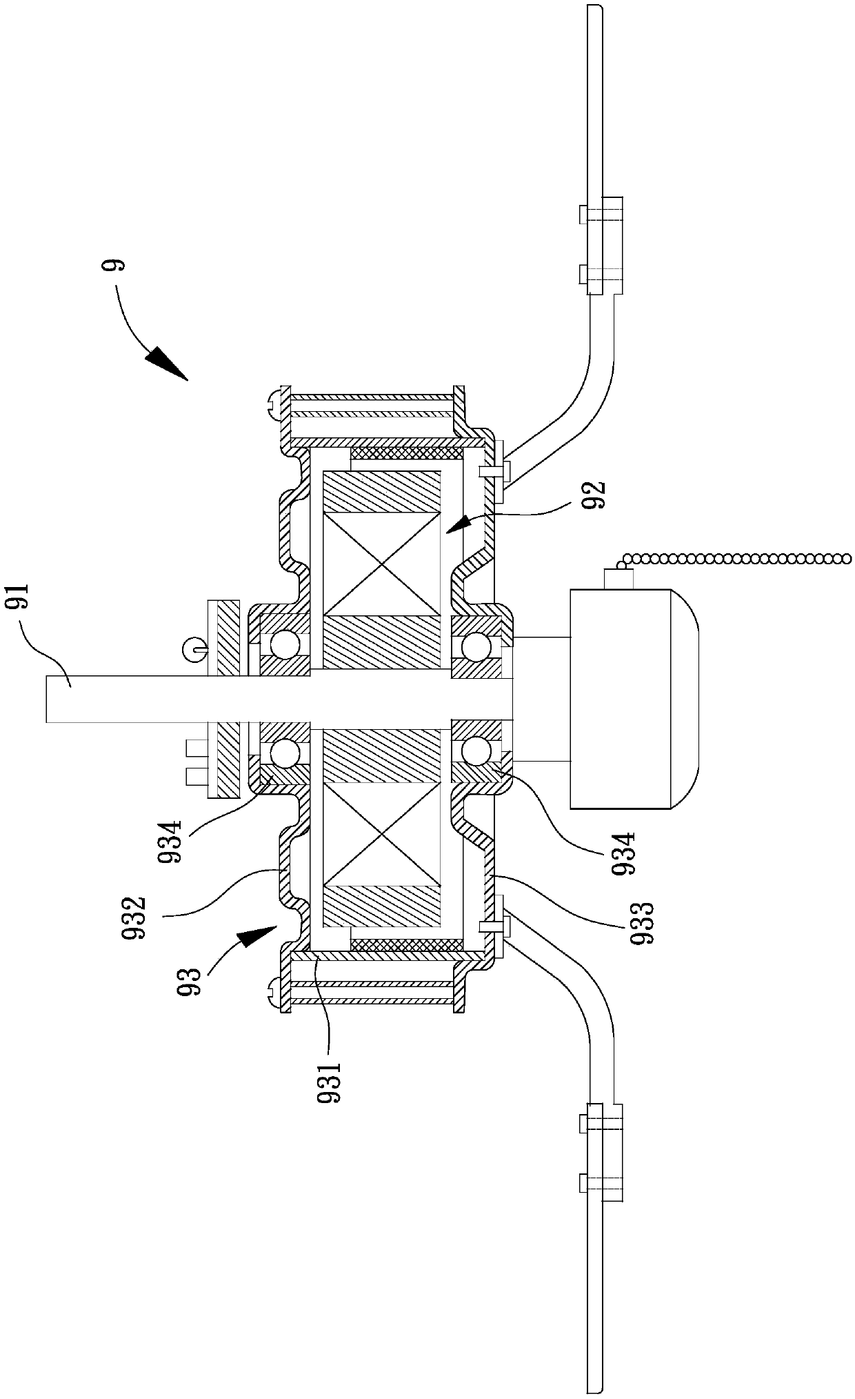
Therefore, when assembling the second aforementioned bearing 934, the stator 92 and other components will increase the load and obstruct the line of sight. In addition to increasing the operational difficulty of the assembly process, it will also cause the coaxiality correction of the two bearings 934 after assembly. It is not easy to carry out, so the assembly procedure of the existing motor 9 is complicated, the technical threshold is high, and the assembly efficiency is difficult to improve

Method used


Image

  • Motor
  • Motor
  • Motor

Examples


Embodiment Construction

[0070] In order to make the above-mentioned and other objects, features and advantages of the present invention more comprehensible, the following is based on the preferred embodiments of the present invention and is described in detail as follows in conjunction with the accompanying drawings:

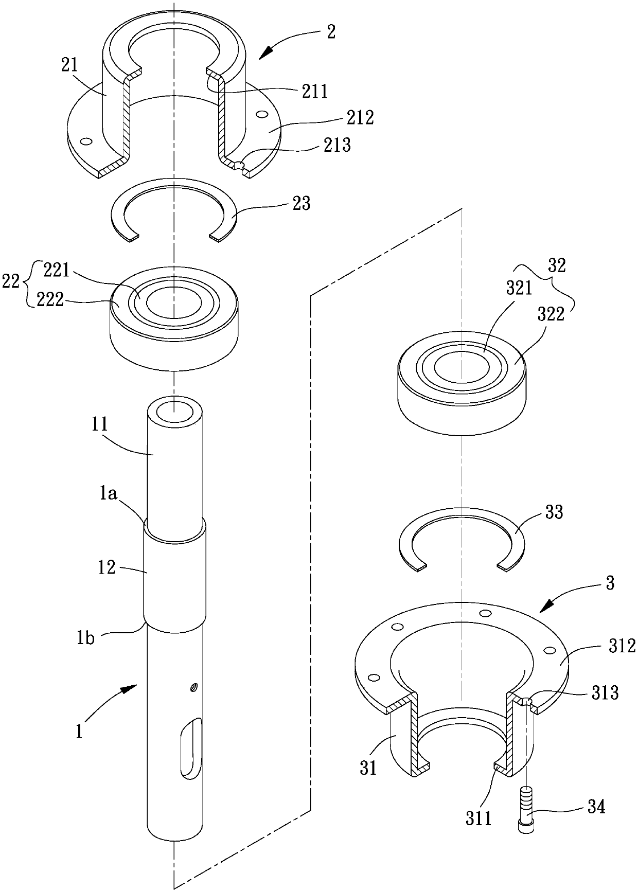
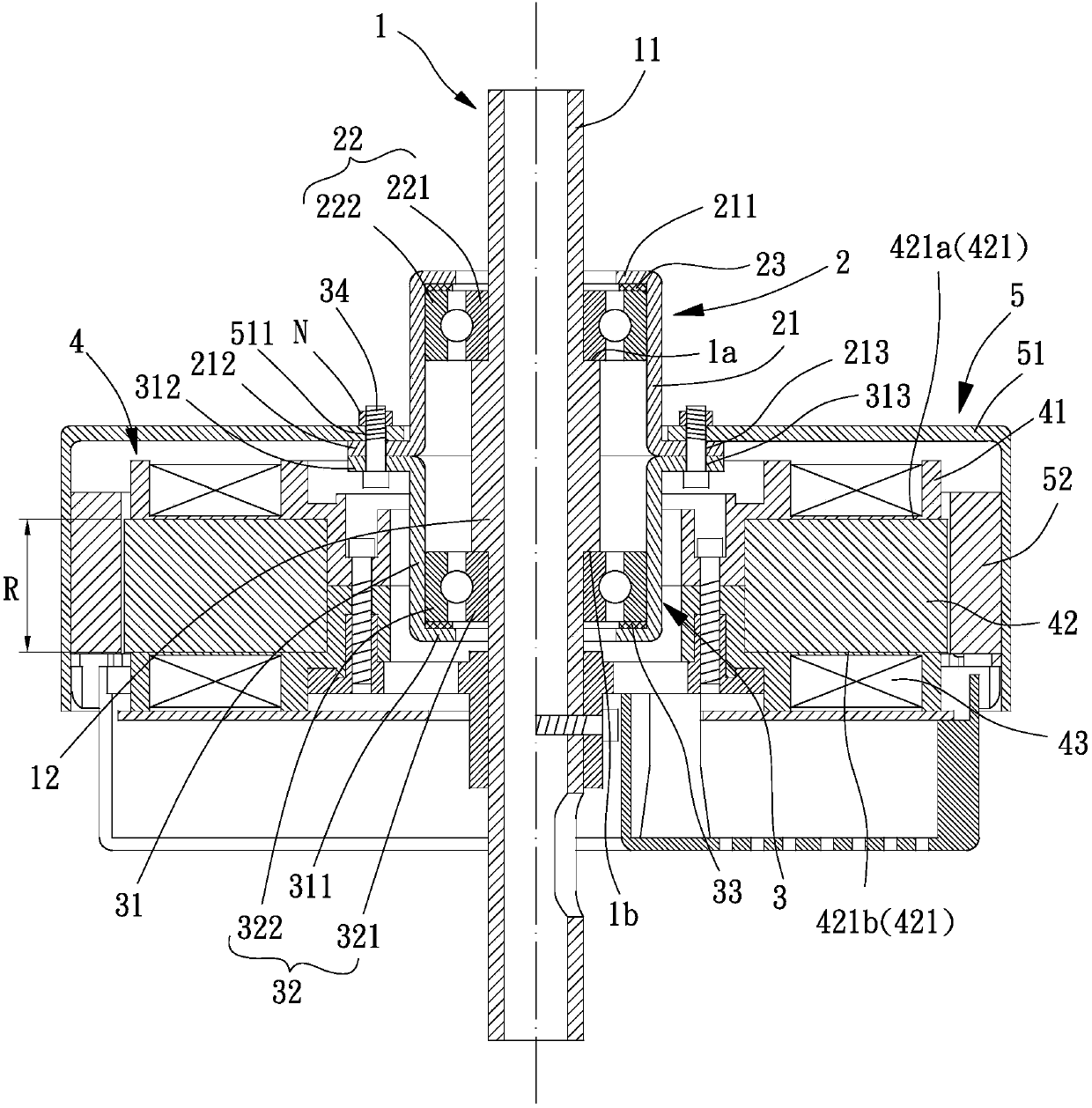
[0071] Please refer to figure 2 , 3 , which is the first embodiment of the motor of the present invention; for example but not limited to, the motor of the present invention is preferably used in a ceiling fan, and the motor generally includes a core shaft 1, a first bearing set 2, a second A bearing set 3, a stator 4 and a rotor 5, the first bearing set 2, the second bearing set 3 and the stator 4 are respectively assembled and positioned on the mandrel 1, and the rotor 5 is combined with the first bearing Set 2 or the second bearing set 3 .

[0072] The mandrel 1 has a first shoulder 1 a and a second shoulder 1 b for assembling and positioning the first bearing set 2 and the secon...


PUM


Abstract

A motor is provided to solve the problem where the assembly of the conventional motor is inconvenient. The motor includes a shaft having a first shoulder portion and a second shoulder portion, a firstbearing assembly including a first bearing received in a first sleeve and clamped by the first sleeve and the first shoulder portion, a second bearing assembly including a second bearing received ina second sleeve and clamped by the second sleeve and the second shoulder portion, a stator coupled with an outer periphery of the shaft and including an iron core, and a rotor coupled with the first or second bearing assembly. The shaft includes. The first and second sleeves are coupled with each other.

Description

technical field [0001] The invention relates to a motor, especially a motor with good assembly convenience. Background technique [0002] Please refer to figure 1 , it is a kind of existing motor 9, and this existing motor 9 has a shaft center 91, a stator 92 and a rotor 93. The center of the stator 92 is combined with the axis 91; the rotor 93 has a middle ring 931 connecting an upper shell 932 and a lower shell 933, and the upper shell 932 and the lower shell 933 are respectively provided with a bearing 934 for the The shaft 91 passes through, so that the stator 92 can be fixed between the upper shell 932 and the lower shell 933 . Embodiments similar to the existing motor 9 have been disclosed in patent cases such as Taiwan Publication No. I326959, No. I555312 and No. I566504. [0003] However, the rotor 93 of the existing motor 9 is directly combined with the shaft center 91 through the two bearings 934. Therefore, in order to ensure that the rotor 93 can rotate around...

Claims


Application Information

Patent Timeline
IPC IPC(8): H02K5/173
CPCH02K5/1732F04D25/062F04D25/088
Inventor 洪银树蔡仲豪
Owner SUNONWEALTH ELECTRIC MACHINE IND
Learn More