
Buckle

A buckle and connecting module technology, applied to buckles, fasteners, clothing, etc., can solve problems such as laborious and inconvenient actual operation

Pending Publication Date: 2019-11-12
LIAN YANG PLASTIC (SHEN ZHEN) CO LTD
View PDF0 Cites 1 Cited by
  • Summary
  • Abstract
  • Description
  • Claims
  • Application Information

AI Technical Summary

Problems solved by technology

This kind of magnetic buckle needs to be pressed hard when it is unlocked. It either needs to be operated by both hands to unlock it, or it will apply the pressing force to the occupant, and it is unlocked by lifting it up. It needs to overcome the magnetic force when lifting it. It can only be unlocked by pulling up with a large force, so its actual operation is not convenient and laborious
[0005] To sum up, although the existing buckle is convenient to lock, its unlocking method still needs to be improved, so as to better meet the daily habits of the public, and is more labor-saving and easy to operate

Method used


Image

  • Buckle
  • Buckle
  • Buckle

Examples


Embodiment 1

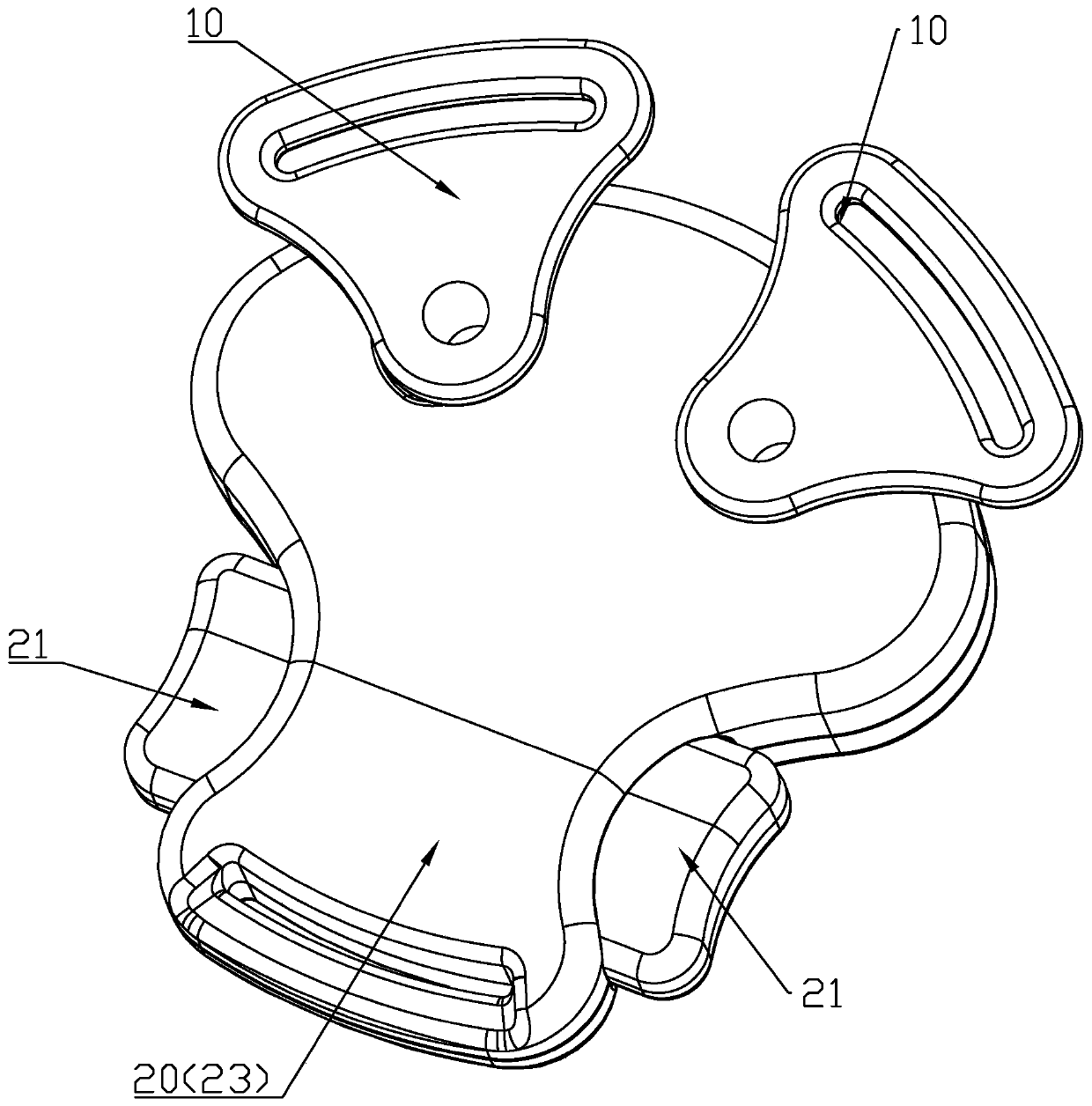
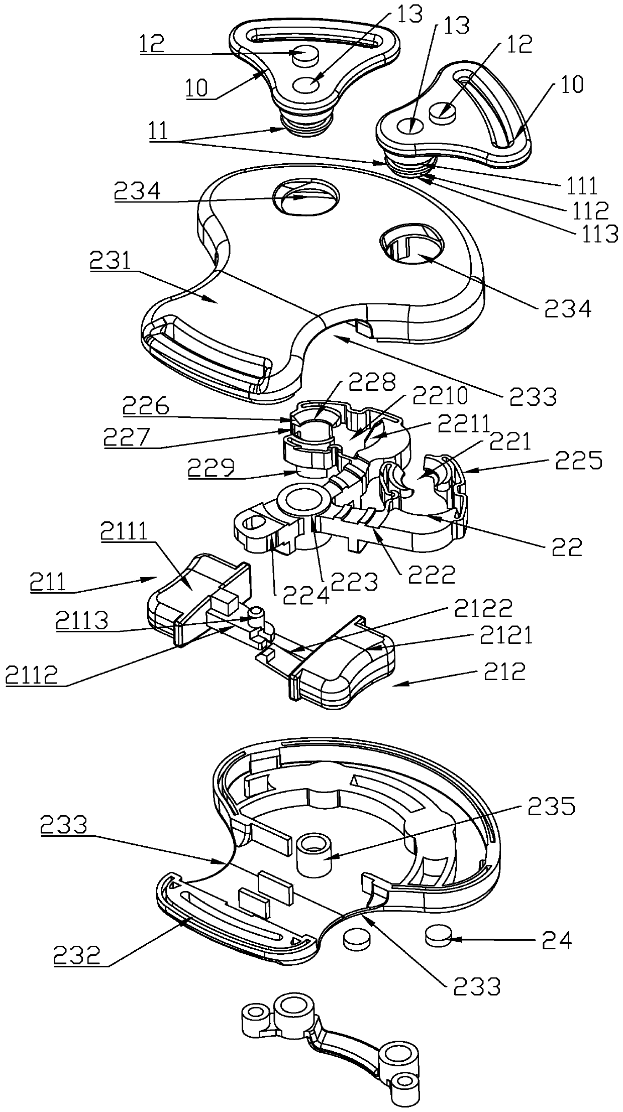
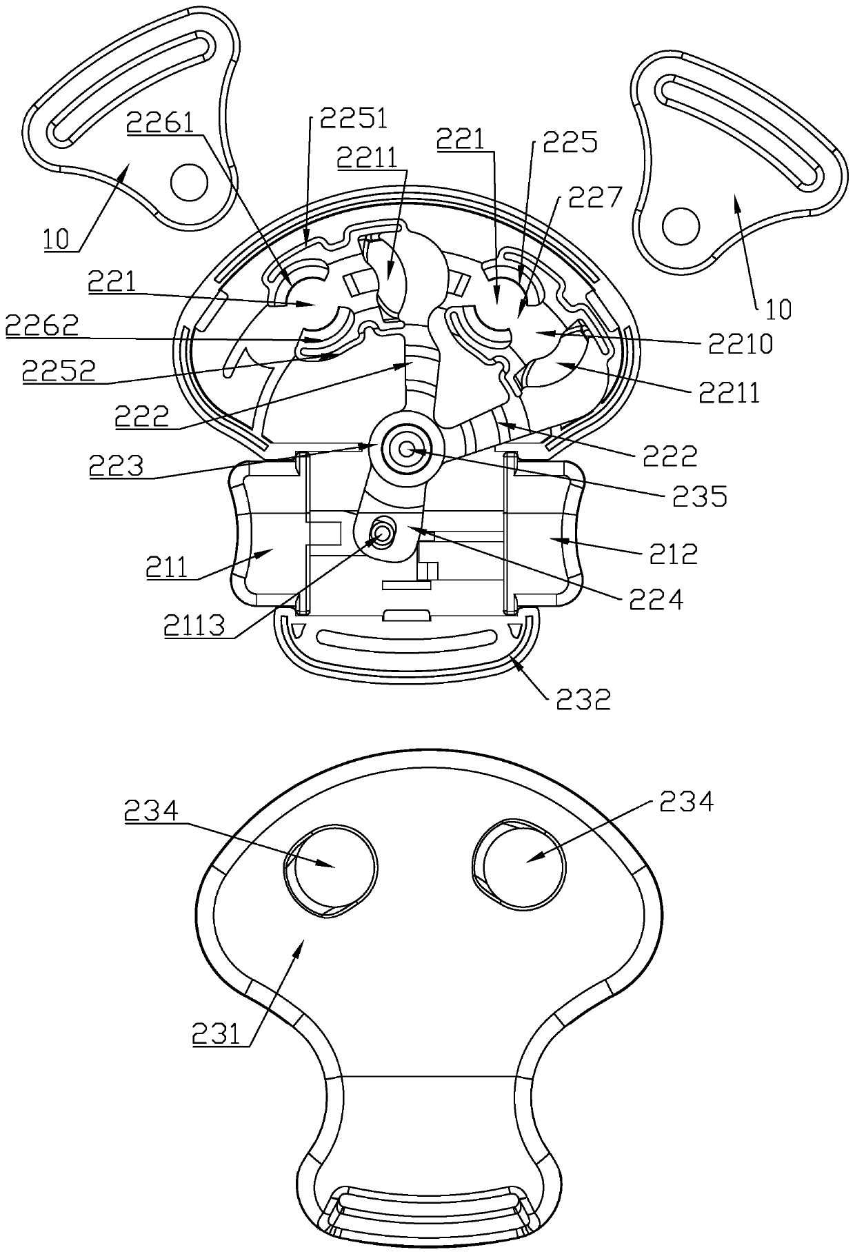
[0072] Such as Figure 1 to Figure 4 As shown, the buckle in this embodiment includes two first connection modules 10 and one second connection module 20 ; the first connection module 10 includes a lock tongue 11 and a first magnet 12 . The second connection module 20 includes a housing 23 , an unlocking operation part 21 , an unlocking linkage part 22 and a second magnet 24 . The unlocking operating member 21 includes a first operating member 211 and a second operating member 212 .

[0073] Such as Figure 1 to Figure 4 As shown, the shape of the first connection module 10 can be set according to needs, and a protruding locking tongue 11 is respectively arranged on it. The locking tongue 11 can be integrally formed with the housing 23 of the first connection module 10 , or can be fixedly connected together. The structure of the locking tongue 11 can refer to the known technology, which generally includes a columnar portion 111 and a protruding edge portion 112 . The colum...

Embodiment 2

[0108] Such as Figure 5 ~ Figure 7 As shown, the structure of the first embodiment is basically the same as that of the first embodiment, except that the unlocking operation member 21 only includes the first operation member 211 and does not include the second operation member 212 . The unlocking operation member 21 is arranged on one side of the housing 23. When in use, pressing the unlocking operation member 21 in one direction can also drive the unlocking linkage member 22 to rotate around the first rotating shaft 235, so that The unlocking link 22 can change from the first position state to the second position state, so as to unlock the first connection module 10 and the second connection module 20 which are locked together.

Embodiment 3

[0110] Such as Figure 8 ~ Figure 11 As shown, the buckle of this embodiment includes a plurality of first connecting modules 10 and one second connecting module 20 ; the first connecting modules 10 include lock tongues 11 and first magnets 12 respectively. The second connection module 20 includes a housing 23 , an unlocking operation part 21 , an unlocking linkage part 22 and a second magnet 24 . Wherein, the unlocking operation part 21 and the unlocking linkage part 22 are integrally formed, and they appear as one part in terms of physical structure.

[0111] Such as Figure 8 ~ Figure 11 As shown, the shape and quantity of the first connecting modules 10 can be set according to needs, and a protruding locking tongue 11 is respectively provided on them. The locking tongue 11 can be integrally formed with the housing 23 of the first connection module 10 , or can be fixedly connected together. The structure of the locking tongue 11 can refer to the known technology, which g...


PUM


Abstract

The invention provides a buckle, wherein the buckle is provided with an unlocking linkage member that is linked by an unlocking operation member, the limitation on a spring bolt is released by disengaging an elastic adjusting hole from a fixing hole, so that the spring bolt can freely enter and exit a locking hole for unlocking, in the process of disengaging the elastic adjusting hole from the fixing hole, and sucked portions of a first magnet and a second magnet are removed by a guide portion, so that the first magnet and the second magnet are separated by a certain distance, thereby reducingthe suction between the magnets to reduce the opening force. Further, a lead-out surface disposed on the guide portion can guide the spring bolt to move toward a direction away from a second connecting module, and can further assist a first connecting module and the second connecting module to separate from each other. Further, the buckle is further provided with a third magnet, after the elasticadjusting hole is disengaged from the fixing hole, the third magnet can move to a position corresponding to the first magnet to generate repulsive interaction on the first magnet, so that the springbolt can be rejected out from the locking hole to separate the first connecting module from the second connecting module.

Description

【Technical field】 [0001] The invention relates to a buckle, in particular to a buckle which is easy to operate and conforms to ergonomics. 【Background technique】 [0002] Some parts of children's products such as strollers, child safety seats, and baby carriers usually need to be connected or maintained in a certain state through buckles. Fasteners are used to realize this variable state connection. Usually, most of the buckles are plug-in safety buckles, which require the user to use both hands to align and lock the mating male buckle and the female buckle to achieve a safe connection. But in reality, users often need to hold the child in one hand and operate the safety buckle with the other. Therefore, this plug-in safety buckle is inconvenient to operate and cannot meet the needs of various scenarios. Therefore, magnetic buckles are gradually used. Buckle to solve this problem. [0003] A magnetic buckle is a buckle that achieves locking through magnetic attraction. It...

Claims


Application Information

Patent Timeline
IPC IPC(8): A44B11/25
CPCA44B11/2503A44B11/2546
Inventor 李邱宗
Owner LIAN YANG PLASTIC (SHEN ZHEN) CO LTD
Learn More