Retracting and releasing device for chain

A technology of retractable device and chain, which is applied to the parts of the binding machine, etc., can solve problems such as ramming and safety hazards, and achieve the effect of improving stability and safety

Active Publication Date: 2014-09-24
ZHEJIANG TOPSUN LOGISTIC CONTROL CO LTD
View PDF9 Cites 17 Cited by
  • Summary
  • Abstract
  • Description
  • Claims
  • Application Information

AI Technical Summary

Problems solved by technology

When in use, fix the upper and lower hooks of the hand chain tensioner to tighten the goods. When the chain is manually tightened, turn the handle to further tighten the chain. force, and the force gradually increases during the process of tightening the chain; when the chain needs to be loosened, reverse the handle to disengage the worm from the worm wheel, and the force directed to the housing will slowly be consumed during this process, However, since the stroke of the worm and the worm wheel is fixed, when the worm and the worm wheel are completely disengaged, the force pointing to the housing may not be consumed. At this time, the fixed end of the chain will rush towards the housing or have a direction towards the housing. The direction is rushing towards the building, and there is a big security risk

Method used


Image

  • Retracting and releasing device for chain
  • Retracting and releasing device for chain
  • Retracting and releasing device for chain

Examples


Embodiment 1

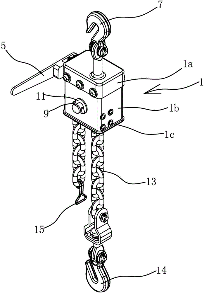
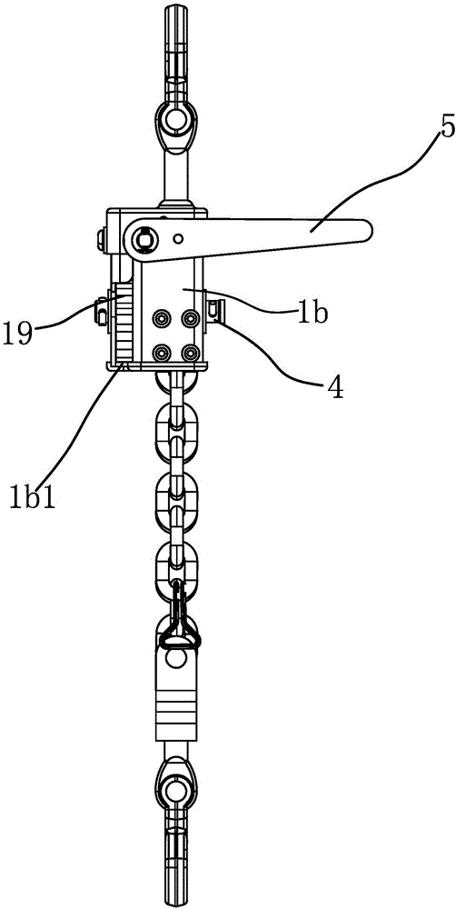
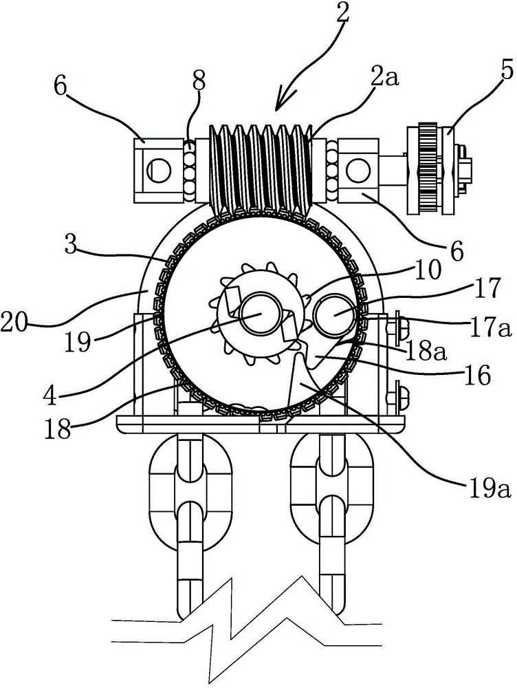
[0053] like figure 1 , figure 2 and image 3 As shown, the retractable device of this chain consists of a housing 1 with a cavity inside, a worm 2, a worm wheel 3, a rotating shaft 4, a pawl 16, an elastic piece, and a ratchet handle 5 {see: Two-way ratchet 10 wrench [Application No.: 201120164696.3; Authorization Announcement No.: CN202129748U]} etc.

[0054] Among them, such as figure 1 As shown, the casing 1 includes an upper casing 1a, a middle casing 1b and a lower casing 1c which are fixedly connected to each other. The inner side of the upper end of the middle casing 1b is provided with a support 6, and the number of the supports 6 is two and the positions are opposite. The fasteners pass through the upper shell 1a and the middle shell 1b and are fixed on the support 6, and the other side of the support 6 is also fixed on the upper end of the middle shell 1b through the fasteners, which can be bolts, screws and other mechanical fasteners. The top of the upper cas...

Embodiment 2

[0071] The structure and principle of this embodiment are basically the same as those of the first embodiment, except that the elastic member is a torsion spring, and the torsion spring is sleeved on the gear shaft 17, one end of the torsion spring acts on the pawl 16, and the other end is fixed Connected to the side of the worm gear 3. And under the action of the torsion spring, the pawl 16 always has a tendency to be embedded in the ratchet teeth of the ratchet wheel 10 .

Embodiment 3

[0073] The structure and principle of this embodiment are basically the same as those of the first embodiment, the difference is that the toggle member is a pressure plate, the pressure plate is hinged on the worm wheel 3 and located on this side of the ratchet wheel 10, and the pressure plate rotates around the hinge point and can be away from the contact The first part 16a or the first contact part 16a abuts against and overcomes the elastic force of the elastic member so that the second contact part 16b is separated from the ratchet 10 . The surface of the casing 1 has a circular opening, the pressing plate includes a grip portion and a contact portion for contacting with the ratchet teeth of the pawl 16 , and the grip portion partially protrudes from the opening. The handle part extends out of the opening, and the hand holds the part of the handle part outside the casing to facilitate the rotation of the pressing plate.


PUM


Abstract

The invention provides a retracting and releasing device for a chain and belongs to the technical field of machines; the problem that a traditional hand chain tensioner is unsafe when the chain is loosened is solved by the retracting and releasing device provided by the invention. The retracting and releasing device for the chain comprises a shell of which the interior is a cavity; a revolving shaft is arranged in the shell; one end of the revolving shaft is fixedly connected with a chain wheel; the chain is twined on the chain wheel; both ends of the chain respectively extend out of the shell, and one of both ends of the chain is fixedly connected with a hook I; a worm is also axially and fixedly connected with the interior of the shell; the outer end of the worm extends out of the shell, and is connected with a handle; the other end of the revolving shaft is fixedly connected with a ratchet wheel; the revolving shaft is sheathed with a worm wheel, and the worm wheel is meshed with the worm; the side part, located on the ratchet wheel, of the worm wheel is hinged to a pawl; an elastic part for enabling the pawl to have a tendency of being embedded into ratchets of the ratchet wheel is arranged between the pawl and the worm wheel; the pawl is also provided with a shifting part; the shifting part is shifted through an external force, so that the elasticity of the elastic part can be overcome by the pawl, and the pawl is separated from the ratchets of the ratchet wheel. The retracting and releasing device for the chain has the advantages of simple in structure, and safe when the chain is loosened.

Description

technical field [0001] The invention belongs to the technical field of machinery, and relates to a chain retracting device. Background technique [0002] In logistics operations, it is necessary to bundle the goods to prevent the goods being transported from being damaged or lost due to bumps and vibrations during transportation. A chain tensioner is one such tool for tying up cargo. [0003] For example, a driving mechanism for a manual chain tensioner proposed by the applicant [Application No.: 201220367023.2; Authorization Announcement No.: CN202783850U] includes a shell with a cavity inside, and a chain that can rotate and wrap the chain in the shell The drive mechanism includes a rotating handle, a worm, a worm wheel and a guide. The rotating handle is axially fixed on the housing, the worm wheel is fixedly connected to the sprocket, and the worm is circumferentially fixed with the rotating handle. When meshing, the guides are embedded on the worm teeth of the worm. ...

Claims


Application Information

Patent Timeline
Patent Type & Authority Applications(China)
IPC IPC(8): B65B13/22
Inventor 牛胜良
Owner ZHEJIANG TOPSUN LOGISTIC CONTROL CO LTD
Why Eureka
Try Eureka