Intra-cabin and extra-cabin linkage type cabin door lock mechanism

A technology of internal and external linkage and cabin door lock, which is applied in the direction of aircraft accessories, etc., can solve the problems of unreasonable design, inconvenient operation, and large space occupied by the lock mechanism, and achieve the effect of ingenious and reasonable mechanism design, guaranteed reliability, and high transmission efficiency

Inactive Publication Date: 2016-08-17
CHENGDU FULI WEIHANG TECH CO LTD
View PDF7 Cites 19 Cited by
  • Summary
  • Abstract
  • Description
  • Claims
  • Application Information

AI Technical Summary

Problems solved by technology

[0002] At present, the lock mechanism of the cabin door is mostly one-way operation, which cannot realize the linkage of the handles inside and outside the cabin, and is inconvenient to operate. At the same time, the lock mechanism does not adopt a double insurance design during the locking and unlocking process, resulting in low reliability of the lock mechanism; opening or closing the cabin It is laborious to open the door; the structural layout of the lock mechanism is not compact and the design is unreasonable, resulting in a large space occupied by the lock mechanism, which is not conducive to the installation and maintenance of the lock mechanism

Method used


Image

  • Intra-cabin and extra-cabin linkage type cabin door lock mechanism
  • Intra-cabin and extra-cabin linkage type cabin door lock mechanism
  • Intra-cabin and extra-cabin linkage type cabin door lock mechanism

Examples


Embodiment Construction

[0021] Below in conjunction with accompanying drawing, the present invention is described in detail.

[0022] Best practice:

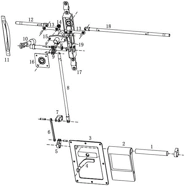
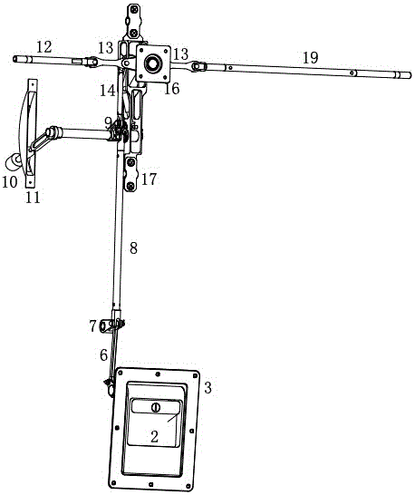
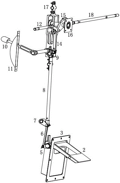
[0023] Such as figure 1 As shown, an internal and external interlocking cabin door lock mechanism includes an external handle 2, an external handle support 3, an external lock 4, a connecting rod I6, a connecting rod II8, an internal handle 10, a left lock pin 12, a connecting rod Rod III 14, lock rocker arm bracket 15, lock mechanism bracket 17 and right lock pin 18.

[0024] The handle support 3 outside the cabin and the rocker arm base 16 are respectively fixed on the cabin door. The handle 2 outside the cabin is connected to the handle support 3 outside the cabin in an embedded form through the rotating shaft 1, and the rotation of the rotating shaft 1 is controlled by the cabin. Outer lock 4 is restricted, one end of the rotating shaft 1 is fixedly hinged with one end of the rotating shaft rocker arm 5, the other end of the rotating shaft rocker...


PUM


Abstract

The invention discloses an intra-cabin and extra-cabin linkage type cabin door lock mechanism. The intra-cabin and extra-cabin linkage type cabin door lock mechanism comprises an extra-cabin handle support and a lock swing arm base, wherein the extra-cabin handle support and the lock swing arm base are fixed to a cabin door. An extra-cabin handle is connected to the extra-cabin handle support and limited by an extra-cabin lock. A rotary shaft is hinged to the lower end of a connecting rod I through a rotary shaft swing arm. The connecting rod I is hinged to the lower end of a connecting rod II through a swing arm. The connecting rod II is fixedly hinged to an intra-cabin handle through an intra-cabin handle swing arm. The lower ends of connecting rods III are also hinged to the hinge point of the upper end of the connecting rod II and the intra-cabin handle swing arm. A left lock pin and a right lock pin are hinged to the two sides of the lock swing arm support through the two connecting rods III correspondingly. One end of a horizontal central shaft of the lock swing arm support is hinged to the lock swing arm base, and the other end of the horizontal central shaft of the lock swing arm support is hinged to a lock mechanism support and can rotate around the central shaft. According to the intra-cabin and extra-cabin linkage operation type cabin door lock mechanism, the cabin door lock mechanism is compact in structure, small in size and low in weight; the mechanism is ingenious and reasonable in design and high in transmission efficiency, and labor is saved in operation; and the dual-insurance design is adopted for the cabin door lock mechanism, operation is easy, and the reliability of the lock mechanism is guaranteed.

Description

technical field [0001] The invention belongs to the field of aircraft or helicopter cabin door auxiliary mechanical devices, and in particular relates to an internal and external linkage type cabin door lock mechanism. Background technique [0002] At present, the lock mechanism of the cabin door is mostly one-way operation, which cannot realize the linkage of the handles inside and outside the cabin, and is inconvenient to operate. At the same time, the lock mechanism does not adopt a double insurance design during the locking and unlocking process, resulting in low reliability of the lock mechanism; opening or closing the cabin It is relatively laborious to open the door; the structural layout of the lock mechanism is not compact and the design is unreasonable, resulting in a large space occupied by the lock mechanism, which is not conducive to the installation and maintenance of the lock mechanism. [0003] The internal and external linkage type cabin door lock mechanism ...

Claims


Application Information

Patent Timeline
Patent Type & Authority Applications(China)
IPC IPC(8): B64C1/14
CPCB64C1/14
Inventor 曾强卢强
Owner CHENGDU FULI WEIHANG TECH CO LTD
Why Eureka
Try Eureka