
A pressure-controlled anti-slamming accelerator control device

A technology of accelerator control and slamming, which is applied to the layout of power plant control mechanism, transportation and packaging, and vehicle parts, etc. It can solve the problems of pedestrian injury, confusion of accelerator and brake, accidents, etc. High frictional force and accident prevention effect

Active Publication Date: 2020-12-25
嘉兴科禾能源科技有限公司
View PDF13 Cites 0 Cited by
  • Summary
  • Abstract
  • Description
  • Claims
  • Application Information

AI Technical Summary

Problems solved by technology

[0003] Although new energy vehicles have many advantages, there are still some problems in the current new energy vehicles. For example, the current car accelerator device is controlled by the foot, but when a novice drives, in an emergency, sometimes the accelerator pedal In the event of confusion with the brakes, the accelerator is pressed hard by mistake, causing the car to accelerate suddenly, resulting in an accident, or even aggravating the accident, causing injury to the driver or passers-by
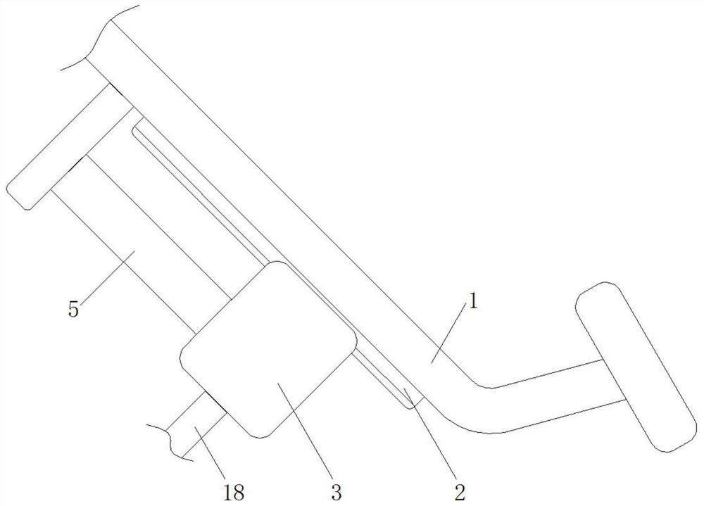
[0004] Therefore, we proposed a pressure-controlled anti-slam accelerator control device to solve the above problems. The sliding of the slider is controlled by the piston and the movable block. When the accelerator is suddenly pressed hard, the accelerator pedal will be caught in the slider The rotating rod is stuck, causing the pedal to be unable to step down, effectively reducing the chance of accidents, and even avoiding accidents

Method used


Image

  • A pressure-controlled anti-slamming accelerator control device
  • A pressure-controlled anti-slamming accelerator control device
  • A pressure-controlled anti-slamming accelerator control device

Examples


Embodiment Construction

[0019] The following will clearly and completely describe the technical solutions in the embodiments of the present invention with reference to the accompanying drawings in the embodiments of the present invention. Obviously, the described embodiments are only some, not all, embodiments of the present invention. Based on the embodiments of the present invention, all other embodiments obtained by persons of ordinary skill in the art without making creative efforts belong to the protection scope of the present invention.

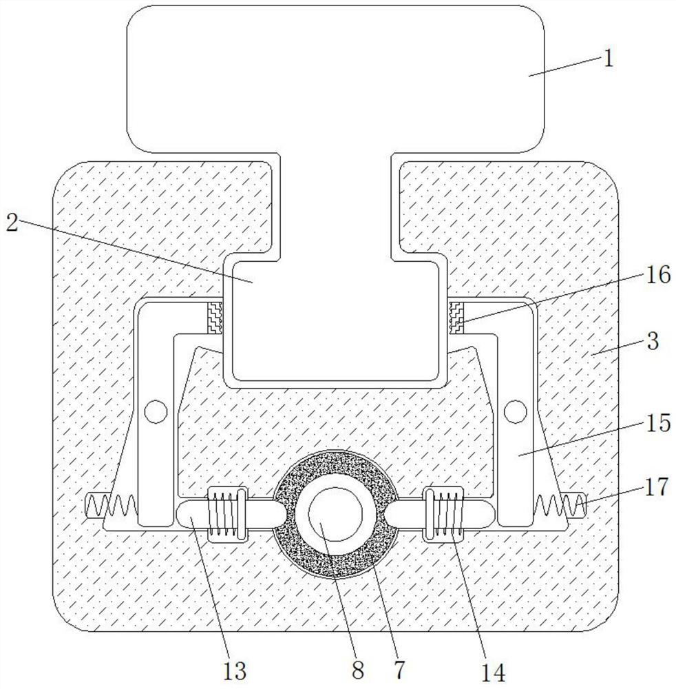
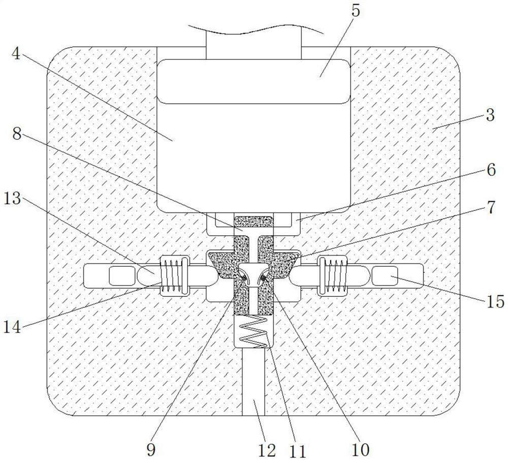
[0020] see Figure 1-4 , a pressure-controlled anti-slam accelerator control device, including a pedal 1, the pedal 1 plays the role of transmission, and the initial state of all structures is as follows figure 1 and image 3 As shown, the material of the pedal 1 is steel material and the width of the pedal 1 is the same as that of the slide rail 2, the material of the slider 3 is aluminum alloy material and the shape of the slider 3 is a cuboid, and the bott...


PUM


Abstract

The invention discloses a pressure-controlled accelerator control device for preventing violently pedaling, and relates to the technical field of new energy automobiles. The pressure-controlled accelerator control device for preventing violently pedaling comprises a pedal, wherein a sliding rail is fixedly connected to the bottom of the pedal, a sliding block is slidably connected to the bottom ofthe sliding rail, and a piston groove is formed in the top of the sliding block. By means of the pressure-controlled accelerator control device for preventing violently pedaling, through the cooperation of the sliding rail and a rotating rod, when a driver suddenly pedals on the accelerator pedal, a piston rod can suddenly squeeze gas into the piston groove, the suddenly increased air pressure can enable soft sheets on the two sides to approach towards the center to block an air leakage port, at the moment, a movable block can move downwards under the action of the air pressure, an exhaust port is staggered with the air leakage port, and the piston rod cannot move downwards continuously; and meanwhile, the movable block can jack jacking blocks to the two sides, and the jacking blocks jackthe rotating rod to rotate, so that a rubber pad is clamped with the sliding rail to increase the friction force, the effect of preventing violently pedaling is achieved, further aggravation of accidents is effectively avoided, and even the accidents can be avoided.

Description

technical field [0001] The invention relates to the technical field of new energy vehicles, in particular to a pressure-controlled anti-slam accelerator control device. Background technique [0002] New energy vehicles are environmentally friendly vehicles with no pollution and zero emissions. New energy vehicles have become one of the most widely used types of vehicles on the market, and the number of people buying new energy vehicles has increased significantly. [0003] Although new energy vehicles have many advantages, there are still some problems in the current new energy vehicles. For example, the current car accelerator device is controlled by the foot, but when a novice drives, in an emergency, sometimes the accelerator pedal The situation of confusion with the brakes occurs, and the accelerator is stepped on by mistake, causing the car to accelerate suddenly, resulting in an accident, and even aggravating the accident, resulting in injury to the driver or passers-b...

Claims


Application Information

Patent Timeline
Patent Type & Authority Patents(China)
IPC IPC(8): B60K26/02
CPCB60K26/02
Inventor 唐润辉
Owner 嘉兴科禾能源科技有限公司
Learn More