Multifunctional spine rack

A multi-functional, spinal technology, applied in medical science, fractures, etc., can solve problems such as difficult access to field work areas, aggravated injuries, and weak fixation

Active Publication Date: 2018-12-21
HENAN PROVINCE HOSPITAL OF TCM THE SECOND AFFILIATED HOSPITAL OF HENAN UNIV OF TCM
View PDF7 Cites 2 Cited by
  • Summary
  • Abstract
  • Description
  • Claims
  • Application Information

AI Technical Summary

Problems solved by technology

[0007] In view of the above situation, in order to overcome the defects of the prior art, the present invention provides a multifunctional spine frame, which effectively solves the problems that the existing spine frame is bulky, difficult to transport and store, difficult to

Method used


Image

  • Multifunctional spine rack
  • Multifunctional spine rack
  • Multifunctional spine rack

Examples


Embodiment 1

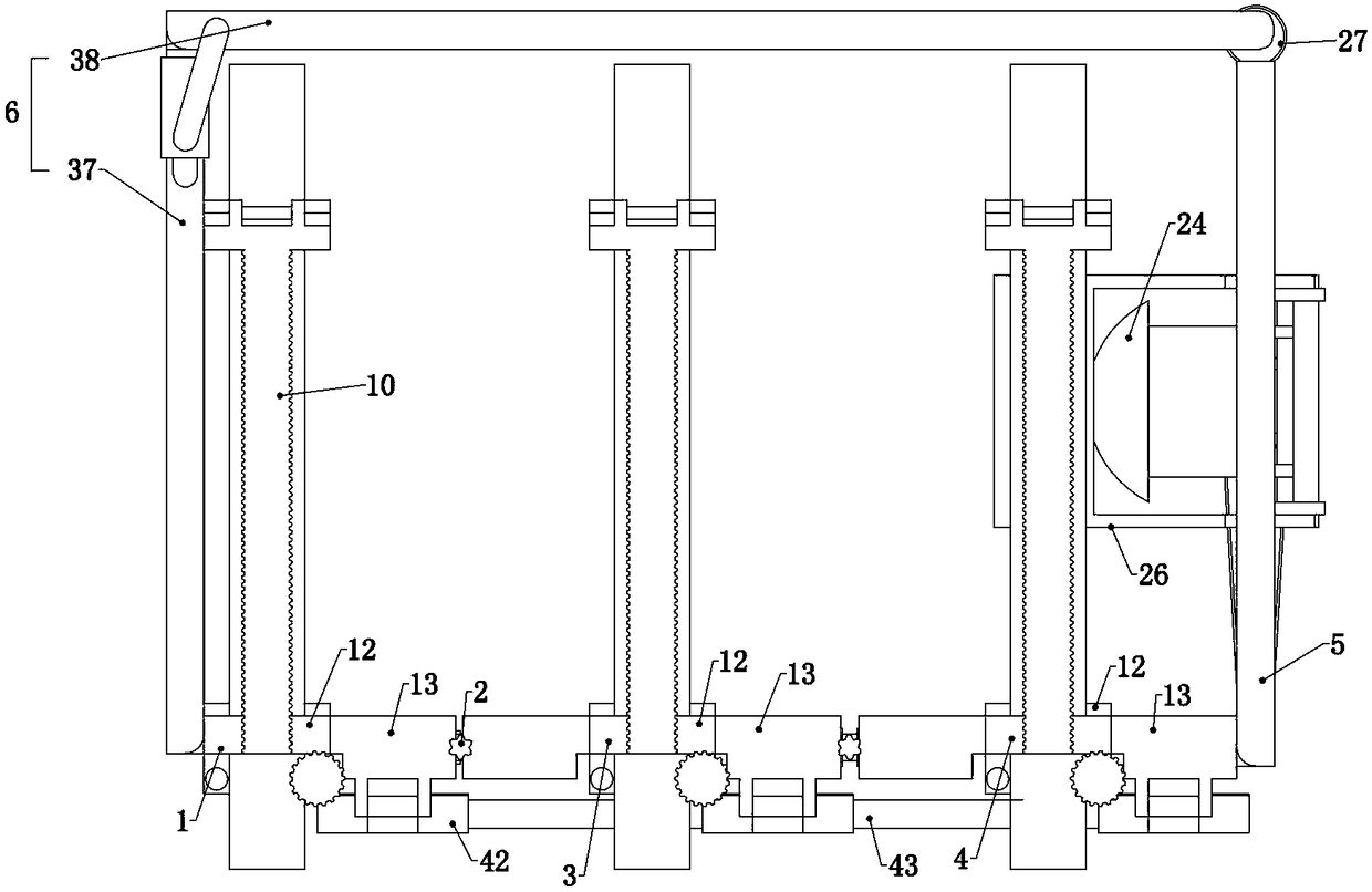
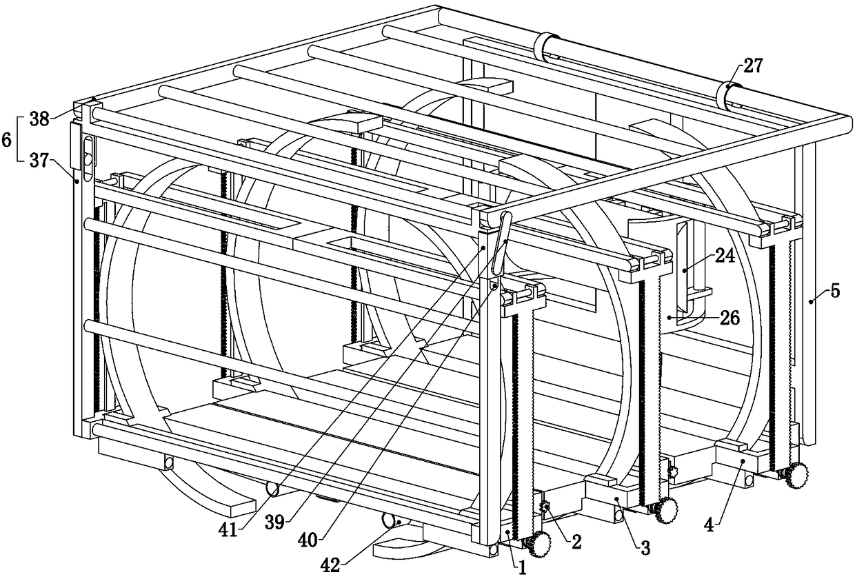
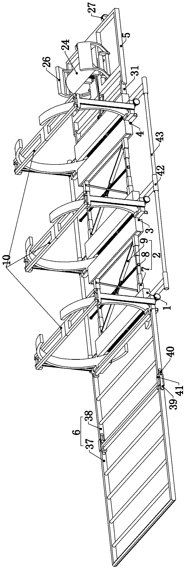
[0040] Embodiment 1, the present invention is a multifunctional spine support, which is characterized in that it includes a waist bracket 1, the waist bracket 1 is used to support the waist of the injured, and the front end of the waist bracket 1 is slidingly connected with a telescopic structure 2 The front end of the telescopic structure 2 is slidingly connected with a back bracket 3, the back bracket 3 is used to support the back of the injured, the front end of the back bracket 3 is slidingly connected with a telescopic structure 2, and the telescopic structure 2 The front end is slidingly connected with a shoulder bracket 4, the shoulder bracket 4 is used to support the injured shoulder 4, the front end of the shoulder bracket 4 is connected with a head bracket 5, and the head bracket The frame 5 is used to support the injured person's head, and the rear end of the waist bracket 1 is rotatably connected with a foldable leg bracket 6, and the leg bracket 6 is used to suppor...

Embodiment 2

[0043] Embodiment 2, on the basis of Embodiment 1, this embodiment provides a specific structure for the X-shaped frame 9, so as to ensure that the X-shaped frame 9 can achieve the automatic extension of the telescopic rod 7 during the approaching process and The function of automatic contraction during the separation process, specifically, the X-shaped frame 9 includes two connecting rods 11 whose middle parts are hinged to each other, and one end of one of the connecting rods 11 is rotatably connected to one end of the telescopic rod 7 The other end of one of the connecting rods 11 is rotatably connected to the other end of the other telescopic rod 7, and the two ends of the other connecting rod 11 are respectively rotatably connected to the two ends of two different telescopic rods 7, that is, the X-shaped The frame 9 is made up of two connecting rods whose middle parts are hinged to each other. The length is fixed, and the ends of the two connecting rods 11 must gradually ...

Embodiment 3

[0044] Embodiment 3, on the basis of Embodiment 2, because the two telescopic rods 7 need to slide horizontally and left and right in addition to vertical expansion and contraction, this embodiment provides a telescopic rod 7 and connected with it. The connection method of the waist bracket 1, specifically, the waist bracket 1 includes a slide rail 12, the slide rail 12 is used to fix the fixing device 10, and the rear end of the slide rail 12 is rotatably connected with legs The upper bracket 6, the front end of the slide rail 12 is fixedly connected with a supporting plate 13, the supporting plate 13 is used to support the waist of the injured, and simultaneously provides a fixed foundation for connecting with the telescopic rod 7, the supporting plate 13 The front end is provided with a chute 14, and one end of the two telescopic rods 7 can slide left and right in the chute 14 and will not come out. This purpose can be easily realized by a keyway for those skilled in the art...


PUM


Abstract

The invention relates to a multifunctional spine rack, which effectively solves the problems that an existing spine rack is big in size and not easy to transport and store, and cannot be carried conveniently. According to the technical scheme, the multifunctional spine rack comprises a waist bracket, the front end of the waist bracket is connected to a telescopic structure, the front end of the telescopic structure is connected to a back bracket, the front end of the back bracket is connected to the telescopic structure, the front end of the telescopic structure is connected to a shoulder bracket, the front end of the shoulder bracket is connected to a head bracket, and the rear end of the waist bracket is connected to a leg bracket. The telescopic structure comprises two telescopic rods,a telescopic two-way lead screw penetrates through the portion between the telescopic rods, so that the two telescopic rods draw closer to each other when the telescopic two-way lead screw rotates forwards, and an X-shaped rack is rotatably connected between the two telescopic rods, so that the two telescopic rods synchronously stretch when drawing closer to each other and synchronously shrink when separating from each other. The waist bracket, the back bracket, and the shoulder bracket are all provided with fixing devices. The multifunctional spine rack is simple in structure and easy to carry, and can be effectively applied to emergency rescue under various complicated circumstances.

Description

technical field [0001] The invention relates to the technical field of spinal medical instruments, in particular to a multifunctional spinal frame. Background technique [0002] Limb damage or spinal column injury caused by falling from a high altitude often occurs, especially in places where accidents are likely to occur, such as mines and construction sites for field operations. After the injury occurs, before being sent to the hospital for treatment in time, the temporary treatment of the injured is of great significance to the development of the injured's condition. For those with serious injuries, such as those with damaged or dislocated spines, it is often necessary to take temporary measures at the accident scene to stop the bleeding first, fix the dislocated spinal joints, and then transport them to the hospital through a spinal rack. In this process, if it is not handled properly, it will bring irreparable harm to the treatment of the injured, and even cause perman...

Claims


Application Information

Patent Timeline
IPC IPC(8): A61F5/05A61F5/042
CPCA61F5/042A61F5/05
Inventor 刘汝银万龙彭晓艳岳宗进于露王新立冯仲凯王西彬鲁花邵同德
Owner HENAN PROVINCE HOSPITAL OF TCM THE SECOND AFFILIATED HOSPITAL OF HENAN UNIV OF TCM
Why Eureka
Try Eureka