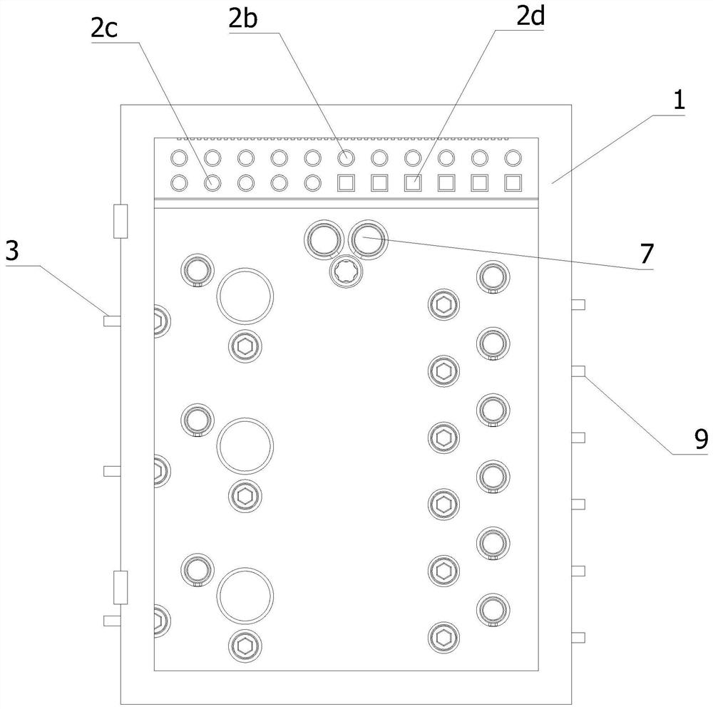
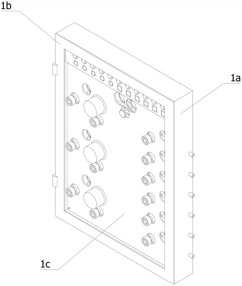
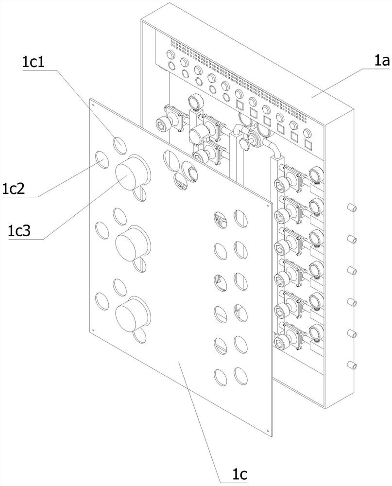
A medical gas area valve box

A valve box and gas technology, applied in valve devices, multi-way valves, mechanical equipment, etc., can solve problems such as inability to switch pipelines, inability to judge air pressure, large switching errors, etc., and achieve the effect of reducing risks

Active Publication Date: 2021-01-22
宁波奉天海供氧净化成套设备有限公司
View PDF1 Cites 0 Cited by
  • Summary
  • Abstract
  • Description
  • Claims
  • Application Information

AI Technical Summary

Problems solved by technology

In this switching method, because the change of the gas flow rate used during work will cause fluctuations in the pressure difference, there will be false switching and two groups of gas supply at the same time, and the switching is unreliable. At the same time, the pressure adjustment mechanism must be manually adjusted after each switching. Pressure reducer, affecting the stability and reliability of the pressure reducer
This switching method has the following problems: it cannot be switched and two groups of gas are supplied at the same time, the switching error is large, only one automatic switching operation can be realized each time, manual assistance is required after switching, and the output gas is unstable
[0008] 1. The pressure sensor is installed in the gas output pipeline after confluence. When the internal pressure of the gas output pipeline decreases, the controller cannot judge which pipeline has the lower internal pressure;
[0009] 2. When the controller or electromagnetic switching valve fails and the gas supply stops or the pipeline cannot be switched, it is impossible to switch the pipeline or restore the gas supply by manual means

Method used


Image

  • A medical gas area valve box
  • A medical gas area valve box
  • A medical gas area valve box

Examples


Embodiment Construction

[0062] The technical solutions of the present invention will be further described below in conjunction with the accompanying drawings and through specific implementation methods.

[0063] Wherein, the accompanying drawings are only for illustrative purposes, showing only schematic diagrams, rather than physical drawings, and should not be construed as limitations on this patent; in order to better illustrate the embodiments of the present invention, some parts of the accompanying drawings will be omitted, Enlargement or reduction does not represent the size of the actual product; for those skilled in the art, it is understandable that certain known structures and their descriptions in the drawings may be omitted.

[0064] In the drawings of the embodiments of the present invention, the same or similar symbols correspond to the same or similar components; , "inner", "outer" and other indicated orientations or positional relationships are based on the orientations or positional ...


PUM


Abstract

The invention relates to the field of valve boxes, in particular to a medical gas area valve box. A box body, a controller, a first air inlet pipeline, a second air inlet pipeline, a third air inlet pipeline, a convergence air row, a gas pressure reduction adjusting valve, a flow dividing air row and an air conveying pipeline are included. The convergence air row and the flow dividing air row arein communication through the gas pressure reduction adjusting valve. The air outlet ends of the first air inlet pipeline, the second air inlet pipeline and the third air inlet pipeline communicate with the convergence air row, and the air inlet end of the air conveying pipeline communicates with the flow dividing air row. An air inlet air row is provided with a first air pressure sensor, and the convergence air row is provided with a second air pressure sensor. An emergency air supply pipeline is additionally arranged in the valve box, so that the medical gas source disconnection risk is reduced, each air supply pipeline can be manually opened, and accordingly, the medical gas source disconnection risk is further reduced; and a sound and light alarm can be used for guiding a worker to adjust the gas pressure reduction adjusting valve, and the air pressure value in the flow dividing air row conforms to the total air pressure value required by the opened air conveying pipeline.

Description

technical field [0001] The invention relates to the field of valve boxes, in particular to a valve box in a medical gas area. Background technique [0002] The gas manifold is suitable for enterprises with large gas consumption. Its principle is to input bottled gas to the main pipeline of the manifold through clamps and hoses. After decompression and adjustment, it is transported to the use site through pipelines. It is widely used in hospitals , chemical industry, welding, electronics and scientific research units. The basic performance of the gas manifold connects the gas from multiple steel cylinders to the main manifold through the conduit, and after decompression and stabilization, it is transported to the special equipment by the pipeline to the place of use, so as to ensure that the pressure of the gas source of the gas appliance is stable and adjustable. Generally, there are two One group of gas cylinders, one group of gas supply, one group of backup, manual or aut...

Claims


Application Information

Patent Timeline
Patent Type & Authority Patents(China)
IPC IPC(8): F16K11/22F16K37/00
CPCF16K11/22F16K37/005
Inventor 吴林彬周超陈策
Owner 宁波奉天海供氧净化成套设备有限公司
Why Eureka
Try Eureka